installation &
operating instructions
Design Envelope 4200h & 4280
End Suction Horizontal Pumping Units
39
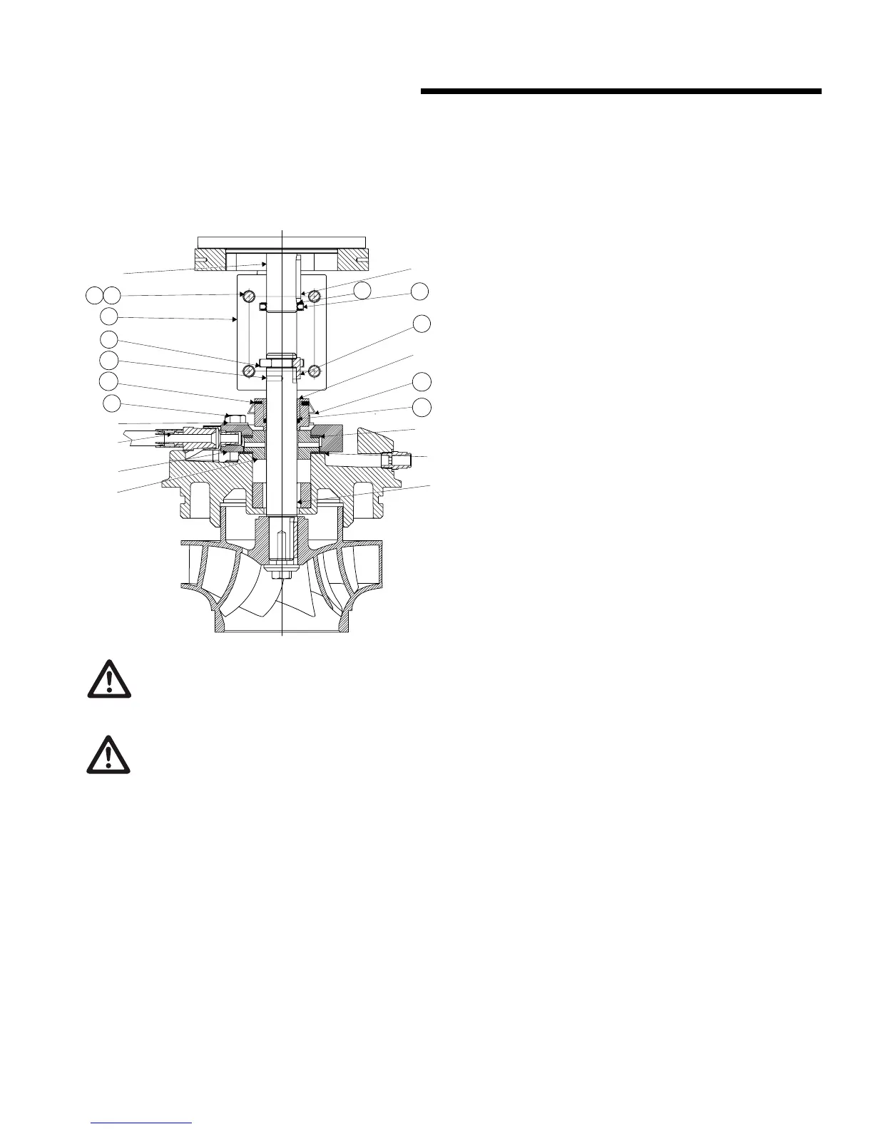
6.3.1 mechanical seal replacement instruc-
tions for rigid split- coupled pumping
units (series 4300, 4200h & 4322)
1
4
1
9
5
5
6
5
6
5
0
2
2
3
140
148
21A
62C
62B
62A
145
155
156
149
163
caution
Do not use oil, Vaseline or other petroleum or silicon
based products for seal elastomer lubrication.
Otherwise elastomer swelling may occur, causing seal
failure. Recommended: International Products Corp p-80
Rubber Lubricant Emulsion in USA & UK www.ipcol.com
Seal Removal
An important feature of the rigid split-coupled pump is that the
design permits removal of the mechanical seal without disturb-
ing the pump, motor or electrical wiring.
a Disconnect the power supply at the main switch and close
the isolating valves on the suction and discharge. Empty
casing by removing drain plug(s) located at the bottom.
b Loosen o the seal collar set screws (62A) Remove the
coupling screws and lock washer (144,145) and separate
the coupling halves (140). Remove the motor shaft key
(05) and the pump shaft key (149).
Do not remove motor collar (155) for seal replacement.
c Remove the mechanical seal rotating assembly (62)
through the gap between the pump and motor shafts..
d Disconnect the seal flush piping (59) from pump discharge.
Mark seal gland plate (54) position. Remove the seal gland
plate bolts and washer (lock washer) (52,163) and seal
gland plate (54). Remove the stationary seat (61) and seat
gaskets (55).
Seal replacement
Handle mechanical seal carefully to protect seal faces from
damage. Do not contaminate seal faces with finger prints
e Replace the stationary seat (61) and gaskets (55) from
mechanical seal package, aligning the seat flush hole with
the seal gland plate flush line connection. Ensure the large
diameter gasket is on the bottom. Replace seal gland plate
(54) and tighten the seal gland plate bolts (52,163) evenly
and diagonally to 5 (ft. lbs) for 0.75" seal size.
f When installing the mechanical seal (62), ensure parts are
perfectly clean.
g Apply a small amount of temporary rubber lubricant emul-
sion to the O-ring (62b). Carefully slide the mechanical seal
rotating assembly (62) down the shaft onto the stationary
seat (61). Do not tighten the set screws (62a) on the side
of the mechanical seal yet. Do not remove holding clips
(62c).
If motor is replaced: Loosen set screws (56) on motor shaft
collar (155) and remove from old motor shaft. To position the
collar (155) correctly on the new motor shaft, temporarily
fit motor shaft collar (155) into groove of the keyed coupling
half. Slide collar, with coupling half onto new motor shaft until
end of shaft lines up with line scored into coupling. Tighten
the visible set screws (156) in the collar (155) enough to hold
the collar in place on the shaft and remove the coupling half.
Tighten all collar set screws (156) evenly and diagonally.
h Fit the motor shaft key (05) and the pump shaft key (149)
then install the keyed coupling half (140) first.
note:
For easier coupling installation, motor and pump shaft keys (05
& 149) should be 180 degrees from the working area. To auto-
matically locate the impeller in the pump, insert the coupling
screw Allan wrench into positioning hole (21a) and lift pump
shaft until the pump shaft collar is positioned in the coupling
groove, then rotate shaft to locate the pump shaft key (149)
into blind keyway in coupling.
i Place the second coupling half into position and tighten the
coupling screws (144,145) following the tightening pattern
shown on the illustration (1-2-3-4).
warning
When reinstalling the clamp, tighten the clamp nut to
90-100 in-lb torque.