installation &
operating instructions
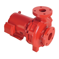
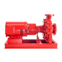
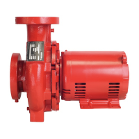
Design Envelope 4200h & 4280
End Suction Horizontal Pumping Units
6
important:
Do not run the pump for any length of time under very
low flow conditions or with the discharge valve closed.
To do so could cause the water in the casing to reach
super heated steam conditions and will cause premature failure
and could cause serious and dramatic damage to the pump and
surrounding area.
1.2 mechanical installation
1.2.1 location
in open systems, locate the unit as close as practical to the
liquid being pumped, with a short, direct suction pipe. Ensure
adequate space is left above and around the unit for operation,
maintenance, service and inspection of parts.
in closed systems, where possible, the pumps should be
installed immediately downstream of the expansion tank /
make-up connection. This is the point of zero pressure change
and is necessary for eective pump operation. Do not install
more than one expansion tank connection into any closed
hydronic system. Electric motor driven pumps should not be
located in damp or dusty location without special protection.
Airflow into the motor and/or motor fan should not be
obstructed.
It is good practice to leave sucient space around equipment
for maintenance and service needs. If the Design Envelope
controls are supplied with integral disconnect switches,
3 6"/ 1 meter clearance may be required in front of the controls
to meet local electrical codes.
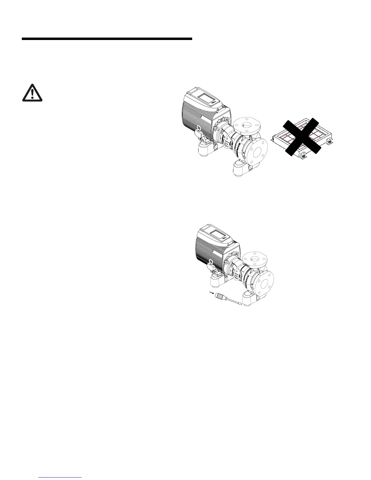
1.2.2 installation
The Design Envelope 4200h and 4280 pumping units 1-10hp
are equipped with integral vibration isolators and do not re-
quire inertia bases or baseplates for horizontal (shaft orienta-
tion), base-mounted installations. The vibration isolators are
pre-sized for the pumping unit and will reduce the transmission
of noise and vibration from the pump and piping system to the
building structure.
fig 1.2.1
The springs use anti-friction neoprene cup mounts and prevent
lateral movement of the pump. If accurate positioning of the
spring cups is required, gently use a tool, such as the end of a
flat-head screwdriver (or crowbar) to tap the cups into place.
fig 1.2.2