installation &
operating instructions
Design Envelope 4200h & 4280
End Suction Horizontal Pumping Units
34
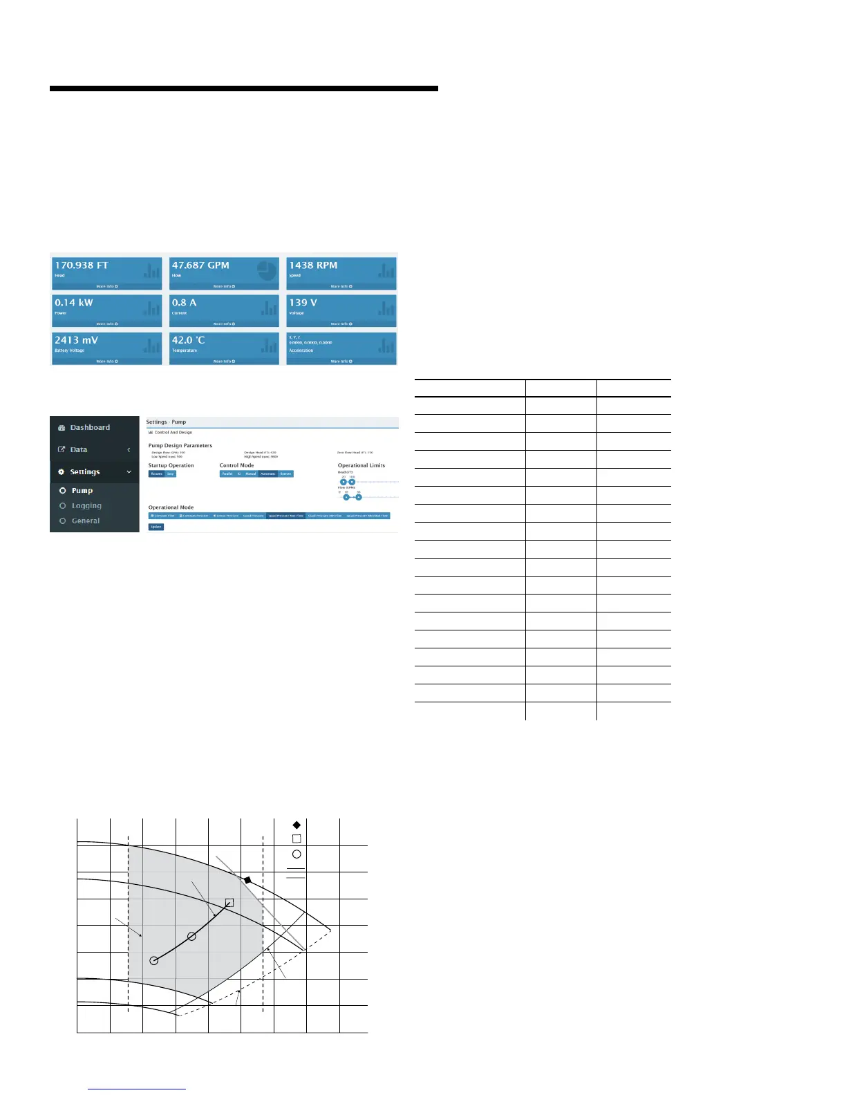
4.4 web interface
At the web browser address bar, type the Pump’s ip (from
Pump’s About screen, Ethernet ip address).
Default user level 1 Password: Armstrong1
To access the control modes:
Press settings Pump
4.5 design envelope flow readout
tolerance
Tolerance on flow and head readings between test stand
instrumentation and Design Envelope controller readout will
be within 5% of bep flow & head values for all Design Envelope
sensorless pump selections.
The same bep flow & head tolerance values will be carried to
the Design Envelope selection point for that model (Guarantee
point, to ansi 40.6 Hydraulic Institute Standard-See fig.4.1),
as follows:
fig. 4.1
The tolerance is applicable when the flow is between 30% and
110% of bep flow at Nominal Pump Speed; and the operating
point is at 54% of Nominal Pump Speed, or greater; and the
motor power is 2hp, or greater.
Flow readouts outside the above limits will be less accurate.
Nominal Pump Speed is displayed as the top speed on any
Design Envelope pump curve.
4.6 noise levels
Motor Maximum Sound Pressure Level
pump model hp [dBA]
1203-001.0 1 69.2
1203-001.5 1.5 72.6
1505-001.5 1.5 62.6
1505H-001.5 1.5 62.6
1505-002.0 2 62.6
1505H-002.0 2 62.6
1505-003.0 3 62.6
1505H-003.0 3 62.6
1505-005.0 5 69.2
1505-007.5 7.5 69.2
0205-001.5 1.5 62.6
0205-002.0 2 62.6
0205-003.0 3 62.6
0205-005.0 5 69.2
0205-007.5 7.5 69.2
2505-003.0 3 62.6
2505-005.0 5 62.6
2505-007.5 7.5 69.2
Sound pressure level measurements made in accordance with iso
3744,± 3dB tolerance (measuring level A-Weighted)
Data based on motor frames at 380-480V. Audible noise is
mainly from the motor fan and will be reduced when operating at
part load.
Quadratic pressure
control curve
BEP
Guarantee &
verification point
Verification point
Head curve
Load limiting curve
End of Envelope
Sensorless Limit
Region of
5% flow & head
accuracy
Minimum speed
Nominal
pump speed
54% Nominal
pump speed
30% BEP flow 110% BEP flow
40% Nominal
pump speed
0
0
10
20
30
40
50
60
70
80
100 200 300 400 500 600 700 800
900
Flow (USgpm)
Quadratic pressure control curve
Head (ft)