installation &
operating instructions
Design Envelope 4200h & 4280
End Suction Horizontal Pumping Units
8
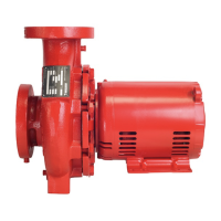
Turn the cast knob clockwise to increase
the free & operating height, or counter-
clockwise to decrease the height. The free
& operating heights by pump model are
listed in the below table
de 4200h/4280,
spring type
free & operating
height
Standard Spring
Isolators
3.75" (95 mm)
Seismic Mount 5.00" (127 mm)
The shrouds can then be re-assembled to the pump by
fastening the 2 halves together around the pump foot and
motor foot. Push the shroud assembly down and ensure the
shroud pins click into the locator holes in the castings.
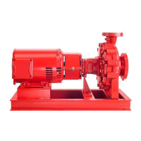
1.2.6 installation for seismic mounts
Pumps equipped with the Seismic Mount option have seismic
mounts factory pre-installed to the feet and must be bolted
to the ground structure. Anchor rods may be either cast-in
place or post-installed. Ensure the anchoring and mounts are
installed along the long side of the pump (as shown in
fig 1.2.6)
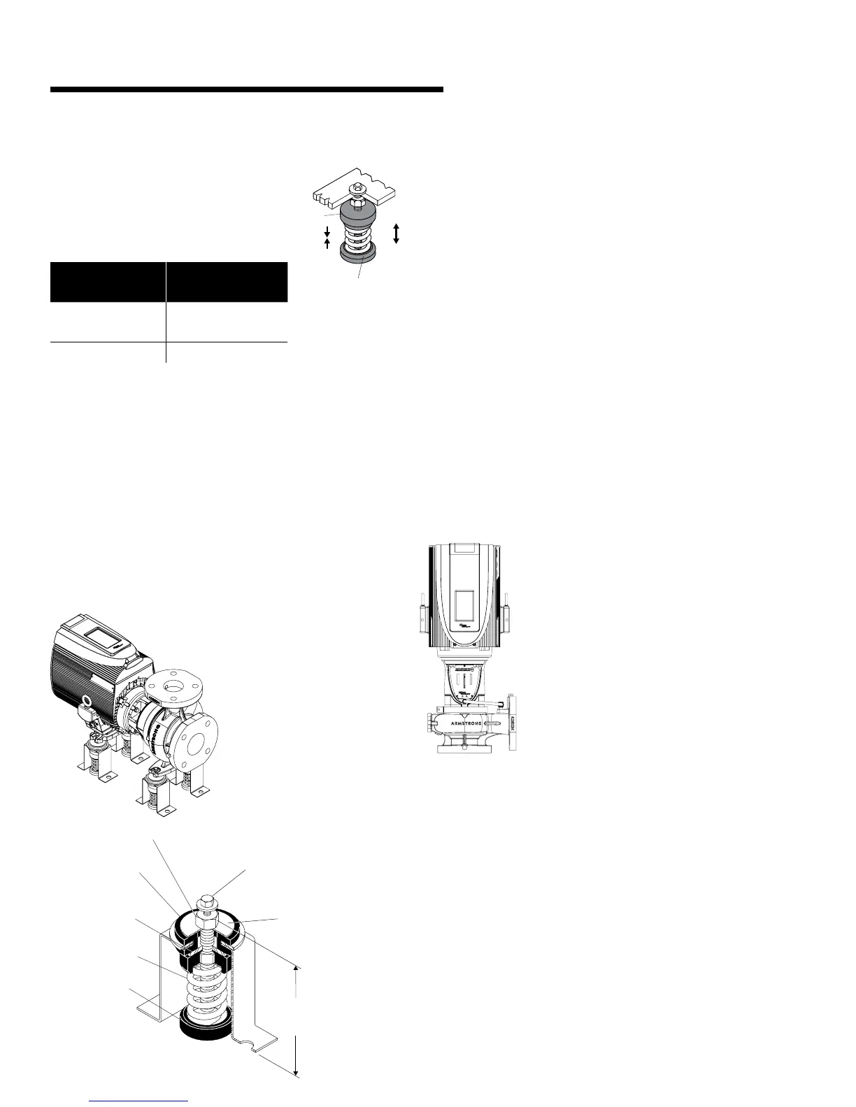
fig 1.2.6
¼" × 1" (25mm)
locking cap screw
height
down stop
adjustment bolt
all-directional
neoprene snubber
upward rebound
plate is adjustable
interchangeable
steel spring
neoprene
acoustical cup
Take 2 full counter-clockwise turns on each leveling bolt and
continue even adjustment of all mounts until all springs are
loaded and mountings are back to Free and Operating Height.
Take no more than two additional counter-clockwise turns on
any leveling bolt to level equipment.
Tighten cap screws to secure equipment.
Adjust plates so there is V" (3mm) clearance between top
of plate and underside of all-directional neoprene cushion. Turn
rebound plates clockwise to lower, or counter-clockwise
to raise.
1.2.7 vertical shaft installation
Design Envelope 4200h and 4280 pumping units 1-10hp may
be safely installed in a vertical shaft orientation as shown in fig
1.2.7. The motor fan must be in an upright position; with the
suction port facing down. When installed vertically, the integral
springs and shrouds should be removed from the base of pump.
fig 1.2.7
1.2.8 pump piping – general
Never connect a pump to piping, unless extra care is taken to
measure and align the piping flanges well. Always start piping
from pump.
Use as few bends as possible and preferably long radius
elbows.
Ensure piping exerts no strain on pump as this could distort
the casing causing breakage or early failure due to pump
misalignment.
All connecting pipe flanges must be square to the pipework and
parallel to the pump flanges.
Turn
cast knob
cw=
ccw=
acoustical cup