Chapter 1 - Hardware Description
3
1-1-2 Integrated I/Os
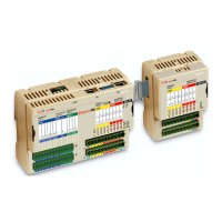
The microPAC base unit can house up to 28 I/O ports:
6 AI 6 analogue inputs configurable for mA, V (terminals E1... E6, F1... F6);
2 AI 2 optional universal or high level isolated analogue inputs configurable for
(terminals E7... E10, F7... F10):
- Thermocouples (TC J, K, L ,N, R, S, T);
- RTD (PT100, PT1000);
- ±mA, ±V linear inputs;
- Potentiometers.
4 AO 4 optional high level analogue outputs (terminals E11... E14, F11... F14);
RS RUN/STOP program functionality (terminal A1);
8 DI General Purpose Digital Inputs (terminals A2... A5, B2... B5);
8 DO
Isolated General Purpose Digital Outputs (terminals A6... A9, B6... B9).
Figure 1.2 - Control Unit I/O and Communication Ports
WARNING
The RESET button does not restart the CPU or the 1131 application.
The RESET button
resets all the stored setup parameters and restores the
defaut parameters
(as well as those set by the user).
RS232/485
Communication/Configuration
Port Connector (X0)
RS485 Modbus
Connector (X1)
Ethernet 10 Base T
port (LAN) + 2 LAN
status LEDs
Run/Stop
terminal (A1)
and RS status
LED
Digital input
terminals
(A2...A4,
B2...B4)
Digital output
terminals
(A6...A9,
B6...B9)
Power Supply
Terminals
= +24 Vac/dc
(A10, A11)
= Ground (B10)
= 0V (B1, B11)
Diagnostics LEDs
• = ERR
• = RUN
• = BAT
• = PWR
Analogue
input
terminals
(E1...E6,
F1...F6
Analogue
input
terminals
(E7...E10,
F6...F10
Analogue
output
terminals
(E11...E14
F11...F14
8 digital output
LEDs (red)
8 digital input
LEDs (yellow)
Expansion bus
connector
Serial ports
X0, X1 activity
LEDs (green)
RESET button
Serial ports
configuration
microswitches

 Loading...