5
Chapter 2
Installation
2-1 Mechanical installation
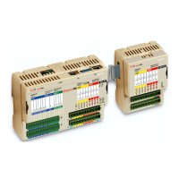
The sigmadue microPAC MP-01 Unit and the additional external expansion I/O
units are designed to be installed on standard DIN rails.
As the MP-01 has only one expansion connector, it must be installed at the left
end of the chain. Up to two additional external expansion I/O units can be
connected in chain to the MP-01.
2-1-1 Installing and Removing the I/O expansion modules
A complete description on how the modules can be mounted on or removed from the
system can be found in the “
MP-01 Installation Manual
”
[9]
.
2-2 Electrical installation
Refer to: “
Figure 1.2 - Control Unit I/O and Communication Ports
” and “
MP-01
Installation Manual
” [9] for details.
2-2-1 Connect the communication cables
RS232/485
Serial Service/
ModBus Port
X0 connector
The connector X0 on the MP-01 unit is an RJ45 type, with the following pinout:
RS485
Modbus Port
X1 connector
The connector X1 on the MP-01 unit is an RJ45 type, with the following pinout:
LAN Ethernet
10baseT
LAN connector
The connector on the CPU module is an RJ45 type, with the following pinout:
Pin 1 2 3 4 5 6 7 8
Signal
D+
(RS485)
D-
(RS485)
GND
(RS485)
GND
(RS232)
RX
(RS232)
TX
(RS232)
NC NC
Pin 1 2 3 4 5 6 7 8
Signal D+ (RS485) D- (RS485) GND (RS485) NC NC NC NC NC
Pin 1 2 3 4 5 6 7 8
Signal TX+ TX- RX+ NC NC RX- NC NC

 Loading...