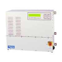
AC08 and AC12 Operations Manual....
16
5.2 ELECTRICAL INSTALLATION
This procedure assumes the physical installation of the converter has been completed. It is the
user’s responsibility to provide input service over-current protection and disconnect means.
Maximum continuous input current for the 8kVA AC08 is 40Amps, and for the 12kVA AC12 is
55Amps. A circuit breaker with a 60Amp rating is recommended.
All power wiring requires the removal of the lower front cover. This cover is secured with 15 ea 6-
32 x ¼” stainless steel screws. Do not remove the upper front cover, or the disconnect
switch/bracket assembly. Place the disconnect switch in the OFF position.
Remove the input service panel from the bottom of the system. This panel is secured with 10 ea 10-
32 x 3/8" stainless steel screws. The input service panel is supplied with two pilot holes for power
wiring strain reliefs. Drill or punch the appropriate holes for the selected strain reliefs. Drill a ¼”
diameter hole in the input service panel for equipment (safety) ground terminations. Re-install the
input service panel using the removed hardware.
INPUT WIRING MUST BE PERFORMED BY A QUALIFIED ELECTRICIAN
FAMILIAR WITH STANDARD SAFEGUARDS AND PROCEDURES REQUIRED
BY THE INSTALLATION OF THIS TYPE OF EQUIPMENT. POWER MUST BE
REMOVED FROM THE INPUT DISTRIBUTION SYSTEMS SUPPLYING
POWER TO THE AC08 OR AC12 PRIOR TO THE START OF THE FOLLOWING
STEPS. INPUT AND OUTPUT POWER MUST BE SECURED (LOCKED) IN THE
OFF (DE-ENERGIZED) STATE UNTIL INSTRUCTED OTHERWISE BY THIS
DOCUMENT.
FAILURE TO FOLLOW THESE PROCEDURES CAN RESULT IN DAMAGE TO
THE EQUIPMENT, AND CAN PRESENT THE RISK OF INJURY OR DEATH TO
THE INSTALLER OR THE OPERATOR.