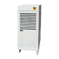
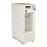
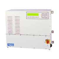
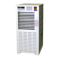
AC24/30/36 Operations Manual....
34
6.4 REMOTE COMMUNICATIONS, cont.
Command Description Comment
:SHORe:ON Shore Power ON Same as pressing the Shore
Power ON button on the
panel.
:SHORe:OFF Shore Power OFF Same as pressing the Shore
Power OFF button on the
panel.
:CONVerter:ON Converter Power ON Same as pressing the
Converter Power ON bttn
on the panel.
:CONVerter:OFF Converter Power OFF Same as pressing the
Converter Power OFF bttn
on the panel.
:TS:CONVerter:ON Transfer from Generator to Converter
:TS:GENerator:ON Transfer from Converter to Generator
:TS:G1:MASTer Set Generator 1 as transfer master Same as pressing the
GENERATOR display
button, then F1
:TS:G2:MASTer Set Generator 2 as transfer master Same as pressing the
GENERATOR display
button, then F2
:AUTOSTART:ON Enable Auto-Restart function
:AUTOSTART:OFF Disable Auto-Restart function
:AUTOSTART:STATe? State query 1=Enabled, 0=Disabled
Command
Description Return Value Range
:SYSTem:CONFiguration System Configuration Integer, 0-65535
:STATus:SW0 Integer, 0-65535
:STATus:SW1 Status Word #1 Integer, 0-65535
:STATus:SW2 Status Word #2 Integer, 0-65535
:STATus:SW3 Status Word #3 Integer, 0-65535
:STATus:G1 Generator #1 Status Integer, 0=OFFLINE,
1=ONLINE
:STATus:G2 Generator #2 Status Integer, 0=OFFLINE,
1=ONLINE
:SYST:ERR 0=Successful Communiqué
-100=Command Error (includes: parity,
framing, and overrun errors)
-200=Execution Error
-300=Device Specific Error
-400=Query Error
!~ Immediate command, Shore Off
!# Immediate command, :STATus:SW0
:MEASure:SP1:FREQuency Shore Power Frequency Real number, 0 to 100
:MEASure:SP1:VLL1 Shore Power 1 Voltage Real number, 0 to 1000
:MEASure:SP1:VLL2 Shore Power 2 Voltage Real number, 0 to 1000