Servicemanual TD60
19
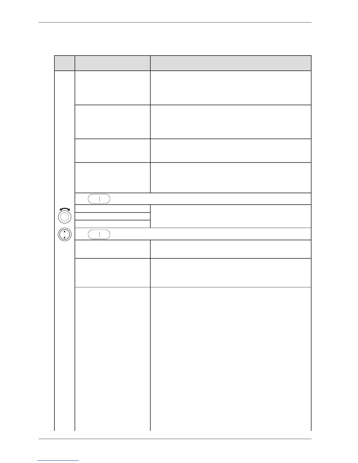
Press/
turn
LCD 2 Comments/instructions
DataSerialNo, Data Ser Num, Data-
SerialNo, DataSerialNo, Serienummer,
Serienummer, Dataversio Nro, N° de
série, Seriennummer, Num. di serie, N°
de serie, Сeрийный нoмeр , Serienum-
mer
Date for programming the software (Year_Week)
CU date code, CU Date Code, CU
date code, CU datum kod, CU dato
kode, Styrekort prod dato, CU pvm
koodi, Code date CU, CU Datums-
code, Codice data CU, Código fecha
CU, Кoд дaты БУ, CU datacode
Control unit’s date of manufacture (Year_Week)
Software, Software, Software, Mjukva-
ra, Software, Software ver., Ohjelmisto,
Logiciel, Software, Software, Software,
Beрсия пpoг., Software
Software version number.
No. of cycles, Number of Cycles, No.
of cycles, Antal cykler , Antal cyklusser,
Antall bruk, Syklien lkm, Nb. de cycles,
Anzahl der Zyklen, Numero cicli, N° de
ciclos, Кoл-вo циклoв, Aantal cycli
Number of cycles/programs run
Press
to exit the service menu.
Testing, Test, Test, Tester, Test, Testaus,
Essai, Test, Test, Test, Teстиpoвaниe,
Testen
Testing Motor, Test motor, Motortest,
Tester motor, Test av motor, Moot-
toritesti, Essai moteur, Test motor, Test
motore, Test motor, Teст мoтopa,
Motor testen
Normal action: The motor will run continuously.
Testing Heater 1, Test heater 1, Ele-
menttest 1, Tester varmelegeme 1, Test
av element 1, Vastustesti 1, Essai él.
chauf 1, Test verw. element 1, Test el.
risc. 1, Test elem calef 1, Teст TЭHa 1,
Heizungstest 1
Motor runs continuously. Heater 1 runs regulated on and off by CU regarding to
measured thermistor values. Total consumption is app. 9A in this mode. If value differs,
do the following:
1. Detach the panel
2. Disconnect electrical connections at the CU.
3. Measure DC Ω for heaters and related wires. For values and measure points, see
chapter ”Components and measurement values” and ”Wiring diagram”.
IF THE VALUES ARE INCORRECT:
Check the electrical function for connections and heater. Change parts if needed.
IF THE VALUES ARE CORRECT:
a) Start the component test (”Test heater 1”)
b) Measure AC voltage directly on the CU (see wiring diagram for measuring points).
Voltage should be the same as power supply net.
c) If values are out of range: Replace the CU.
LCD shows ”_ _ _ _ _ _ _ _ : XX°C YY°C ZZ °C”.
XX = temperature values for thermistor 1
YY = temperature values for thermistor 2
ZZ = temperature values for thermistor 3
>100°C (XX) = short-circuit in thermistor 1 (heating element does not start)
10°C (XX) = thermistor 1 faulty (heating element heats but is only regulated by the
overheating protection).
>100°C (YY) = short-circuit in thermistor 2 (heating element does not start)
10°C? ± 2°C (YY) = thermistor 2 faulty (functions as vented dryer).
150°C (ZZ) = thermistor 3 short-circuited
25°C (ZZ) = thermistor 3 faulty
CONTINUE ON NEXT PAGE
The options below are displayed in the order they occur in LCD 2. All display text language ver-
sions are displayed.
Service menu TD60.3