9
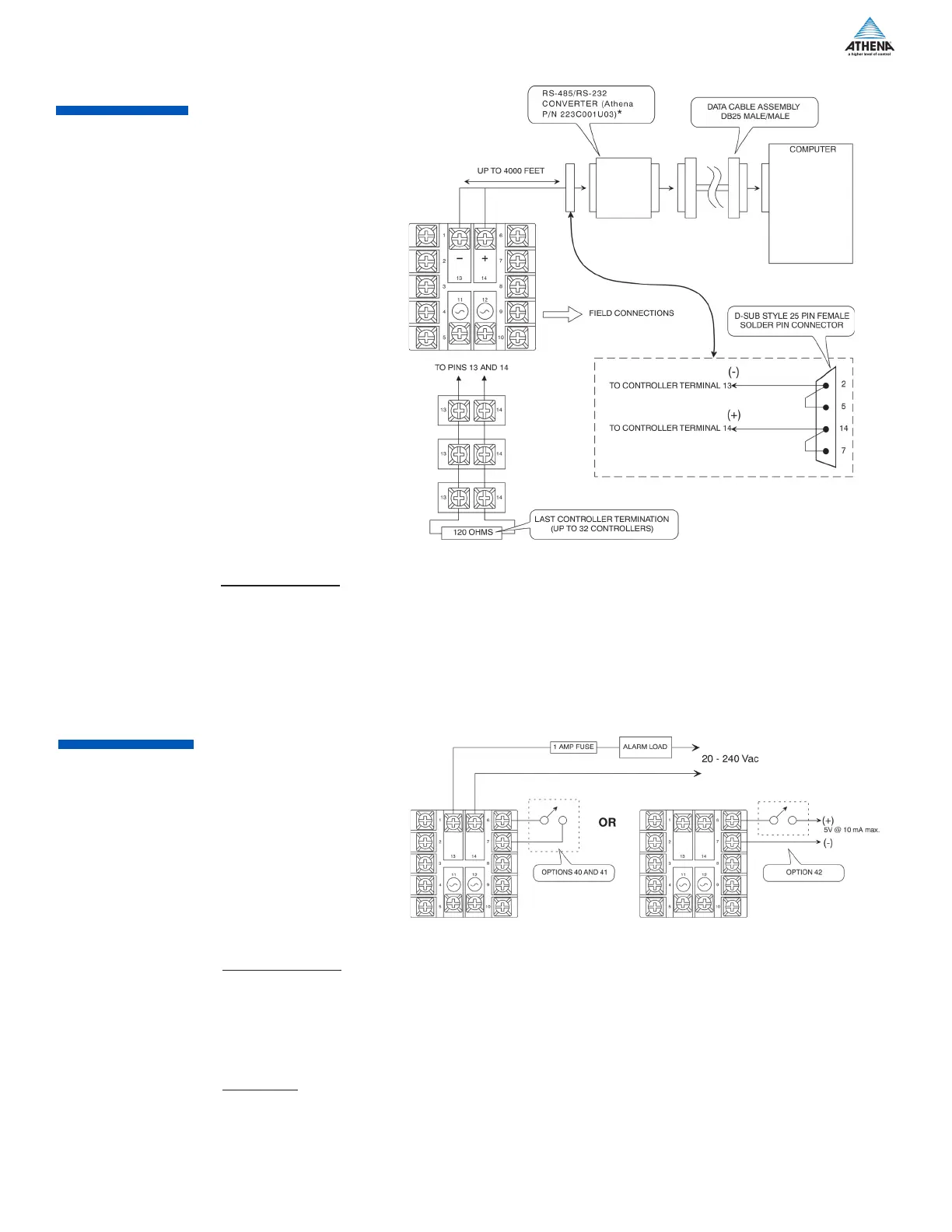
Option Description: Provides one-to-many communications.
If run exceeds 1000 ft., terminate the controller furthest from the computer by connecting a 120-ohm, 1/4-
watt resistor between terminals 13 and 14.
*Converter is supplied with a wallplug-mount power transformer.
Figure 15. Wiring for RS-485 Communications
Option Description:
Dual function board (functions unrelated)
a. Output alarm is energized when either A1 or A2 is active.
b. Digital input controls Remote Standby, Ramp-Soak Run/Hold, OR Second Setpoint Select.
Option 40: Active when switch closed.
Option 41: Active when switch open.
Option 42: Active when 5 V input present
Load Limits:
Max. Load Current: 1 A rms
Min. Load Current: 0.5 mA rms
Power Factor Range: 0.2 to 1.0 (can drive small motors, solenoids, valves, and contactors)
Max. Surge Current, Non-Repeating for 1 second: 7.5 A
Max. I
2
T for fusing (0.01 sec): 4.5 amp-squared secs (1A - ABC1 typical fuse)
Figure 9. Wiring for Contact/Digital Input with Alarm
 Loading...