EasyManua.ls Logo

Athena Controls 16C Series - User Manual

Athena Controls 16C Series
52 pages
Print Icon
To Next Page IconTo Next Page
Loading...
 16C


Question and Answer IconNeed help?

Do you have a question about the Athena Controls 16C Series and is the answer not in the manual?

Athena Controls 16C Series Specifications

General IconGeneral
BrandAthena Controls
Model16C Series
CategoryController
LanguageEnglish

Summary

Introduction to Athena Series 16 C Controller

Precautionary Measures for Controller Handling

Instructs to inspect the instrument for shipping damage and save packing materials.

Key Features of the Athena Series 16 C Controller

Lists the various functionalities and capabilities of the controller.

Regulatory Approvals and Certifications

Lists UL E66598 approval for Temperature Indicating and Regulating Equipment.

Critical Safety Warnings for Instrument Operation

Warns about fire hazards, damage, injury, and electrical connections.

Installation Guide for Series 16 C Controller

Unpacking and Inspecting the Controller

Details steps for inspecting the controller for damage and verifying the order code.

Dimensional Specifications of the Series 16 C Controller

Presents the physical dimensions and cutout size requirements for panel mounting.

Mounting Procedures for the Series 16 C Controller

Describes how to insert the controller through the panel cutout and secure it.

Wiring Guidelines and Best Practices

Terminal Identification for Wiring Connections

Identifies the controller's terminals for alarm, communication, sensor input, and outputs.

Wiring Instructions for Thermocouple Inputs

Details the correct wiring for thermocouple sensors, including extension wires.

Wiring Instructions for RTD Inputs

Explains how to connect 2-wire and 3-wire RTDs, including jumper settings.

Wiring for Process and Power

Wiring Configurations for Optional Features

Introduces wiring for optional hardware modules.

Wiring for Dual Alarm Output Options

Describes wiring for dual alarm outputs (NO/NC) and their load limits.

Wiring for Dual Open Collector Alarm Outputs

Wiring for Dual 24 Vdc Alarm Outputs

Explains wiring for Option #21: Dual 24 V outputs with clamping diodes.

Wiring for Relay Normally Open Alarm Output

Wiring for RS-232 Serial Communications

Details wiring for Option #30: RS-232 (one-to-one) communications.

Wiring for RS-485 Serial Communications

Wiring for Contact;Digital Input with Alarm

Describes wiring for Options #40, #41, #42: Contact/Digital Input with Alarm.

Wiring for Transducer Excitation Options

Wiring for Auxiliary Output Options

Explains wiring for auxiliary output options (60-63).

Wiring for Remote Analog Setpoint Options

Overview of Controller Output Types

Operating the Athena Series 16 C Controller

Front Panel Controls and Indicators Explained

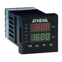
Identifies and describes the function of each button and LED on the controller's front panel.

Initial Power-On Sequence and Configuration

Details the power-on diagnostic checks and initial display sequence.

Recommended Configuration Sequence

Controller Behavior After Power Up

Describes controller output activation, display behavior, and setpoint handling upon power-up.

Step-by-Step Configuration and Startup Guide

Managing Controller Security Levels

Security Level Access Restrictions Overview

Details the different security levels (Key Lockout to Factory) and their access privileges.

Understanding Controller Operating Modes

Lists and describes the available operating modes for the controller.

Detailed Operating Mode Descriptions

Navigating the Controllers Menu System

Explains how to access and navigate the various menus and parameters.

Menu System and Parameter Overview

Detailed Menu Descriptions

Provides a table and descriptions for each main menu (Input, Display, Output, Control, etc.).

Configuring Input Parameters

Input Type Options and Jumper Settings

Lists the available input types and their corresponding jumper settings.

Flowchart for Input Menu Configuration

Typical Sensor Span Ranges

Provides a table of minimum and maximum values for various sensor types.

Setting Parameters for Linear Input Types

Configuring Display Settings

Configuring Output Type and Action

Configuring PID and On;Off Control Parameters

PID Output and Control Parameters

PID Tuning Parameters (Proportional, Derivative, Integral)

Explains the PID tuning parameters: Proportional Band, Derivative, Integral, and Manual Reset.

On;Off Output Parameters

On;Off Control Parameters: Deadband and Hysteresis

Explains the critical On/Off control parameters: deadband and hysteresis.

Configuring Alarm Actions and Operations

Setting Up Alarm 1 and Alarm 2

Understanding Ramp;Soak Recipe Functionality

Configuring Single Setpoint Ramp Time

Explains how to set a ramp from the current process value to the setpoint over a specified time.

Programming Multi-Step Ramp;Soak Recipes

Recipe Menu Options for Ramp;Soak

Details parameters for recipe options like Single Setpoint Ramp and Multi-Step Ramp.

Parameters for Multi-Step Ramp Configuration

Configuring Failsafe States and Loop Break Time

Controller Calibration Procedures

Overview of Available Controller Options

Configuring Communications Parameters (RS-232;RS-485)

Configuring Contact;Digital Input Functions

Configuring Auxiliary Output Settings

Adjusting Autotuning Damping Settings

Autotuning Concepts and Definitions

Defines key terms related to autotuning like Cycle Time, Proportional Band, Integral, and Derivative.

Procedure for Initiating Autotuning

Manual PID Tuning Using Zeigler-Nichols Method

Operating the Controller in Manual Mode (Fixed Output)

Troubleshooting Controller Error Codes

Technical Specifications of the Series 16 C Controller

Summary of Available Alarm Types

Summary of Communication Options

Lists the available serial communication options.

Summary of Digital Input Options with Alarm

Lists the available digital input options.

Summary of RS-485 Modbus Communication Options

Lists the available RS-485 Modbus communication options.

Summary of Transducer Excitation Options

Lists the available transducer excitation options.

Summary of Auxiliary Output;PV Retransmit Options

Lists the available auxiliary output options.

Recalibration Procedures for the Controller

Glossary of Technical Terms and Definitions

Glossary of Control Terms

Frequently Asked Questions (FAQs) about Controller Operation

Additional FAQs on PV Display and Setpoint Changes

Continues the FAQ section, covering PV display flickering and unexpected setpoint changes.

Default and Custom Parameter Settings Reference

Two-Year Limited Warranty and Repair Information