10
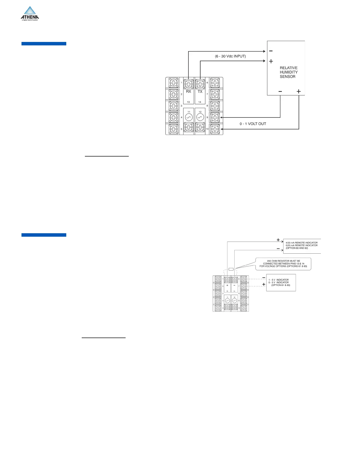
Option Description:
The Setpoint Variable or Process Variable is transmitted to a remote device (chart recorders, indicators, data
recorders, computers, process controllers, etc.) with 1 of 4 different interfaces:
Option 60: 4-20 mA
Option 61: 1-5 V
Option 62: 0-20 mA
Option 63: 0-5 V
The output signal is scalable in the Auxiliary Output Menu. Multiple remote indicators may be driven by the
controller. However, current and voltage outputs cannot be used simultaneously.
For current (mA) options, the remote indicators are connected in series. The sum of the input resistance for
all remote indicators must be less than 400 ohms. For voltage options, the remote indicators are connected
in parallel.
The sum of the currents for all remote indicators must be less than 10 mA.
Figure 18. Wiring for Auxilliary Output
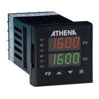
Option Description:
The transducer excitation option provides power to remote transducers. The transducer outputs, in turn,
provide a signal to the controller input which can be scaled in the appropriate engineering units.
Option 50: 10 Vdc
Option 51: 12 Vdc
Option 52: 15 Vdc
Option 53: 5 Vdc
All options will provide at least 20 mA. The transducer circuitry is thermally protected from short circuits.
Figure 16. Wiring for Transducer Excitation
 Loading...