29
8025I–AVR–02/09
ATmega48P/88P/168P/328P
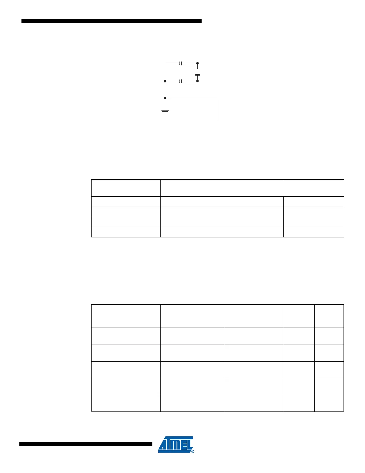
Figure 6-2. Crystal Oscillator Connections
The Low Power Oscillator can operate in three different modes, each optimized for a specific fre-
quency range. The operating mode is selected by the fuses CKSEL3..1 as shown in Table 6-3
on page 29.
Notes: 1. This is the recommended CKSEL settings for the different frequency ranges.
2. This option should not be used with crystals, only with ceramic resonators.
3. If 8 MHz frequency exceeds the specification of the device (depends on V
CC
), the CKDIV8
Fuse can be programmed in order to divide the internal frequency by 8. It must be ensured
that the resulting divided clock meets the frequency specification of the device.
The CKSEL0 Fuse together with the SUT1..0 Fuses select the start-up times as shown in Table
6-4.
Table 6-3. Low Power Crystal Oscillator Operating Modes
(3)
Frequency Range
(1)
(MHz)
Recommended Range for
Capacitors C1 and C2 (pF) CKSEL3..1
0.4 - 0.9 – 100
(2)
0.9 - 3.0 12 - 22 101
3.0 - 8.0 12 - 22 110
8.0 - 16.0 12 - 22 111
Table 6-4. Start-up Times for the Low Power Crystal Oscillator Clock Selection
Oscillator Source /
Power Conditions
Start-up Time from
Power-down and
Power-save
Additional Delay
from Reset
(V
CC
= 5.0V) CKSEL0 SUT1..0
Ceramic resonator, fast
rising power
258 CK 14CK + 4.1 ms
(1)
000
Ceramic resonator, slowly
rising power
258 CK 14CK + 65 ms
(1)
001
Ceramic resonator, BOD
enabled
1K CK 14CK
(2)
010
Ceramic resonator, fast
rising power
1K CK 14CK + 4.1 ms
(2)
011
Ceramic resonator, slowly
rising power
1K CK 14CK + 65 ms
(2)
100
XTAL2 (TOSC2)
XTAL1 (TOSC1)
GND
C2
C1