43
7598H–AVR–07/09
ATtiny25/45/85
In safety level 1, WDE is overridden by WDRF in MCUSR. See “MCU Status Register –
MCUSR” on page 40 for description of WDRF. This means that WDE is always set when WDRF
is set. To clear WDE, WDRF must be cleared before disabling the Watchdog with the procedure
described above. This feature ensures multiple resets during conditions causing failure, and a
safe start-up after the failure.
Note: If the watchdog timer is not going to be used in the application, it is important to go through a
watchdog disable procedure in the initialization of the device. If the Watchdog is accidentally
enabled, for example by a runaway pointer or brown-out condition, the device will be reset, which
in turn will lead to a new watchdog reset. To avoid this situation, the application software should
always clear the WDRF flag and the WDE control bit in the initialization routine.
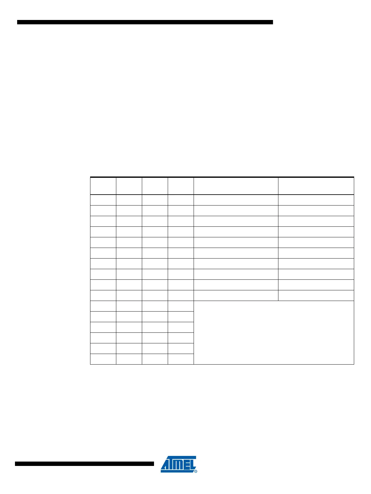
• Bits 5, 2..0 – WDP3..0: Watchdog Timer Prescaler 3, 2, 1, and 0
The WDP3..0 bits determine the Watchdog Timer prescaling when the Watchdog Timer is
enabled. The different prescaling values and their corresponding Timeout Periods are shown in
Table 8-7.
Note: 1. If selected, one of the valid settings below 0b1010 will be used.
Table 8-7. Watchdog Timer Prescale Select
WDP3 WDP2 WDP1 WDP0
Number of WDT Oscillator
Cycles
Typical Time-out at
V
CC
= 5.0V
0000 2K cycles 16 ms
0001 4K cycles 32 ms
0010 8K cycles 64 ms
0011 16K cycles 0.125 s
0100 32K cycles 0.25 s
0101 64K cycles 0.5 s
0110 128K cycles 1.0 s
0111 256K cycles 2.0 s
1000 512K cycles 4.0 s
1001 1024K cycles 8.0 s
1010
Reserved
(1)
1011
1100
1101
1110
1111
 Loading...


