355
7679H–CAN–08/08
AT90CAN32/64/128
• Capture-DR: The content of the selected Flash byte is captured into the Flash Data Byte
Register. The AVR automatically alternates between reading the low and the high byte for
each new Capture-DR state, starting with the low byte for the first Capture-DR encountered
after entering the PROG_PAGEREAD command. The Program Counter is post-incremented
after reading each high byte, including the first read byte. This ensures that the first data is
captured from the first address set up by PROG_COMMANDS, and reading the last location
in the page makes the program counter increment into the next page.
• Shift-DR: The Flash Data Byte Register is shifted by the TCK input.
25.9.2 Data Registers
The data registers are selected by the JTAG instruction registers described in section “Program-
ming Specific JTAG Instructions” on page 353. The data registers relevant for programming
operations are:
• Reset Register
• Programming Enable Register
• Programming Command Register
• Flash Data Byte Register
25.9.2.1 Reset Register
The Reset Register is a Test Data Register used to reset the part during programming. It is
required to reset the part before entering Programming mode.
A high value in the Reset Register corresponds to pulling the external reset low. The part is reset
as long as there is a high value present in the Reset Register. Depending on the Fuse settings
for the clock options, the part will remain reset for a Reset Time-out period (refer to “Clock
Sources” on page 38) after releasing the Reset Register. The output from this data register is not
latched, so the reset will take place immediately, as shown in Figure 23-2 on page 302.
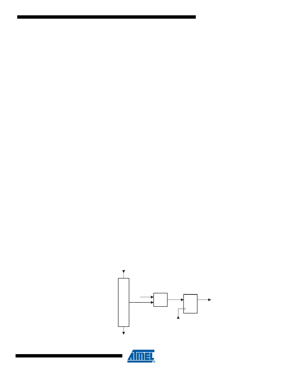
25.9.2.2 Programming Enable Register
The Programming Enable Register is a 16-bit register. The contents of this register is compared
to the programming enable signature, binary code 0b1010_0011_0111_0000. When the con-
tents of the register is equal to the programming enable signature, programming via the JTAG
port is enabled. The register is reset to 0 on Power-on Reset, and should always be reset when
leaving Programming mode.
Figure 25-10. Programming Enable Register
TDI
TDO
D
A
T
A
=
DQ
ClockDR & PROG_ENABLE
Programming Enable
0xA370

 Loading...


