356
7679H–CAN–08/08
AT90CAN32/64/128
25.9.2.3 Programming Command Register
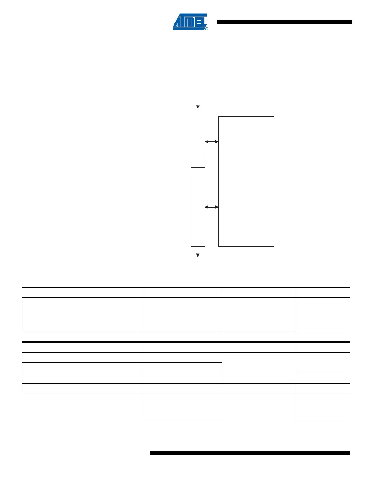
The Programming Command Register is a 15-bit register. This register is used to serially shift in
programming commands, and to serially shift out the result of the previous command, if any. The
JTAG Programming Instruction Set is shown in Table 25-16. The state sequence when shifting
in the programming commands is illustrated in Figure 25-12.
Figure 25-11. Programming Command Register
TDI
TDO
S
T
R
O
B
E
S
A
D
D
R
E
S
S
/
D
A
T
A
Flash
EEPROM
Fuses
Lock Bits
Table 25-16. JTAG Programming Instruction
Set
a = address high bits, b = address low bits, H = 0 - Low byte, 1 - High Byte, o = data out, i = data in, x = don’t care
Instruction TDI Sequence
(1)(2)
TDO Sequence
(1)(2)
Notes
1a. Chip Erase
0100011_10000000
0110001_10000000
0110011_10000000
0110011_10000000
xxxxxxx_xxxxxxxx
xxxxxxx_xxxxxxxx
xxxxxxx_xxxxxxxx
xxxxxxx_xxxxxxxx
1b. Poll for Chip Erase Complete 0110011_10000000 xxxxxox_xxxxxxxx
(4)
2a. Enter Flash Write 0100011_00010000 xxxxxxx_xxxxxxxx
2b. Load Address High Byte 0000111_aaaaaaaa xxxxxxx_xxxxxxxx
(11)
2c. Load Address Low Byte 0000011_bbbbbbbb xxxxxxx_xxxxxxxx
2d. Load Data Low Byte 0010011_iiiiiiii xxxxxxx_xxxxxxxx
2e. Load Data High Byte 0010111_iiiiiiii xxxxxxx_xxxxxxxx
2f. Latch Data
0110111_00000000
1110111_00000000
0110111_00000000
xxxxxxx_xxxxxxxx
xxxxxxx_xxxxxxxx
xxxxxxx_xxxxxxxx
(3)

 Loading...


