55
7679H–CAN–08/08
AT90CAN32/64/128
(V
BOT+
in Figure 7-5), the delay counter starts the MCU after the Time-out period t
TOUT
has
expired.
The BOD circuit will only detect a drop in VCC if the voltage stays below the trigger level for
longer than t
BOD
given in Table 7-3.
Figure 7-5. Brown-out Reset During Operation
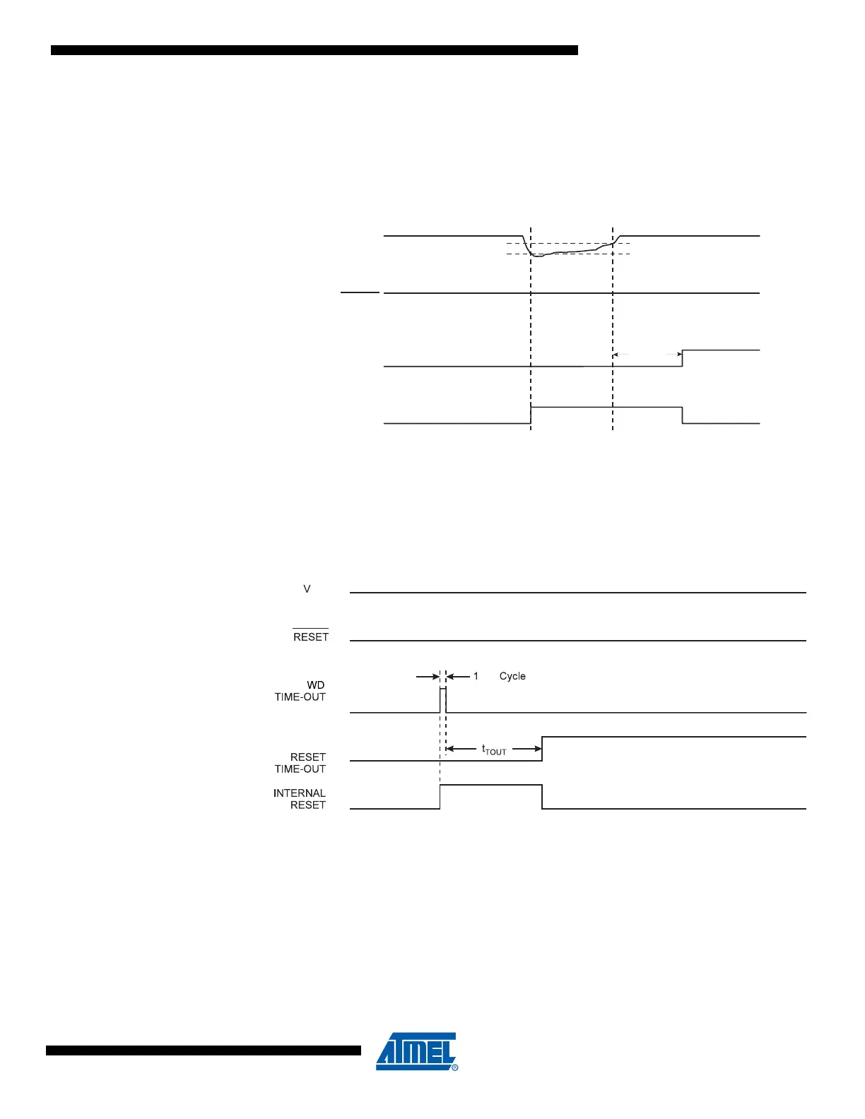
7.1.6 Watchdog Reset
When the Watchdog times out, it will generate a short reset pulse of one CK cycle duration. On
the falling edge of this pulse, the delay timer starts counting the Time-out period t
TOUT
. Refer to
page 57 for details on operation of the Watchdog Timer.
Figure 7-6. Watchdog Reset During Operation
V
CC
RESET
TIME-OUT
INTERNAL
RESET
V
BOT-
V
BOT+
t
TOUT

 Loading...


