79
7679H–CAN–08/08
AT90CAN32/64/128
• A14 – Port C, Bit 6
A14, External memory interface address 14.
• A13 – Port C, Bit 5
A13, External memory interface address 13.
• A12 – Port C, Bit 4
A12, External memory interface address 12.
• A11 – Port C, Bit 3
A11, External memory interface address 11.
• A10 – Port C, Bit 2
A10, External memory interface address 10.
• A9 – Port C, Bit 1
A9, External memory interface address 9.
• A8 – Port C, Bit 0
A8, External memory interface address 8.
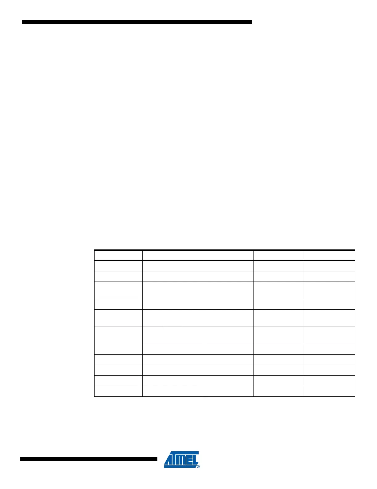
Table 9-10 and Table 9-11 relate the alternate functions of Port C to the overriding signals
shown in Figure 9-5 on page 72.
Note: 1. CKOUT is one if the CKOUT Fuse is programmed
Table 9-10. Overriding Signals for Alternate Functions in PC7..PC4
Signal Name PC7/A15 PC6/A14 PC5/A13 PC4/A12
PUOE SRE • (XMM<1) SRE • (XMM<2) SRE • (XMM<3) SRE • (XMM<4)
PUOV 0 0 0 0
DDOE
CKOUT
(1)
+
(SRE • (XMM<1))
SRE • (XMM<2) SRE • (XMM<3) SRE • (XMM<4)
DDOV 1 1 1 1
PVOE
CKOUT
(1)
+
(SRE • (XMM<1))
SRE • (XMM<2) SRE • (XMM<3) SRE • (XMM<4)
PVOV
(A15 • CKOUT
(1)
) +
(CLKO • CKOUT
(1)
)
A14 A13 A12
PTOE 0 0 0 0
DIEOE 0 0 0 0
DIEOV 0 0 0 0
DI – – – –
AIO – – – –

 Loading...


