FMB10 User’s Manual Edition 06/2005
___________________________________________ Page 10 _____________________________________________
Audemat-Aztec SA – Audemat-Aztec INC
WEB: www.audemat-aztec.com - e-mail: contact@audemat-aztec.com
2.7 “COMO” port : RS232 and auxiliary signals, rear panel
•
permits the configuration of the RDS encoder parameters, via a PC or terminal. Several protocols are
possible including ASCII for the FMB10 encoder (see relevant chapters.
• For the FMB10 encoder : COM0 permits the remote control of the encoder for example via a satellite or
earth link
• For the FMB10 encoder, COM0 permits the transmission of dynamic RDS information (Free format
RDS groups etc...)
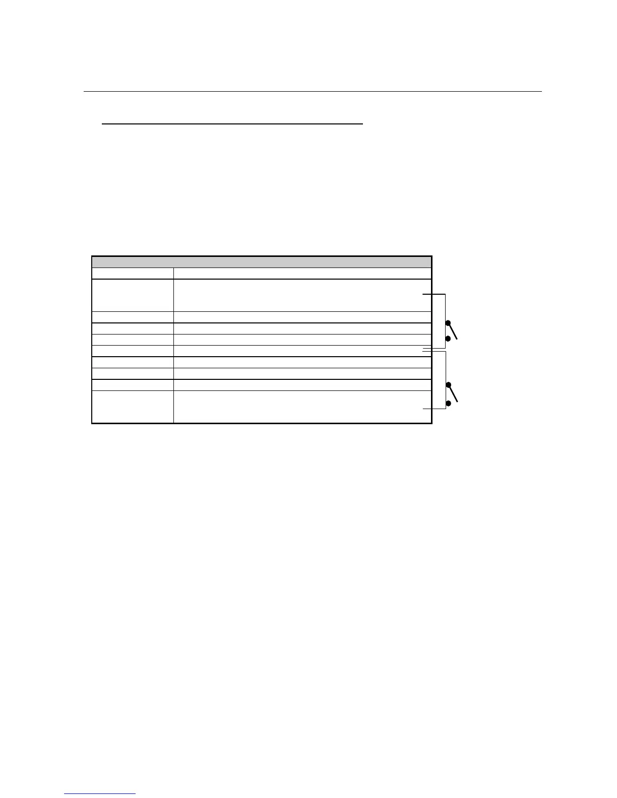
RS232 PORT "COM0" (FMB10 encoder)
Pin Signal
1 According to the configuration of the strap "XS1" to be
soldered, this pin permits the switching of the TA parameter
with an external switch.
2 TX of RDS encoder (DCE)
3 RX of RDS encoder (DCE)
4 connected to pin 6 of the same connector
5 RDS encoder ground
6 connected to pin 4 of the same connector
7 connected to pin 8 of the same connector via buffer
8 connected to pin 7 of the same connector via buffer
9 According to the configuration of XS2 to be soldered, this pin
permits the switching between PI1 and PI2, PS1 and PS2,
with an external switch.
ON:
TA=1
OFF:
TA=0
ON:
PI2/PS2
OFF:
PI1/PS1