Copyright © 2006-2009 AudioNote Kits
www.AudioNoteKits.com
audionotekits@rogers.com
Page 47
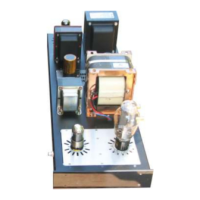
The cable should be laid down the center of the amplifier as shown here.
The ends will connect to their associated Driver Board - make sure that the Left
input goes to the Left driver board (and similar for the Right channel).
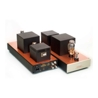
Here you can see the AN-A cable connected to the ECF80
board.
The red lead connects to the INPUT signal and the copper
tinned lead connects to the S. GND input!
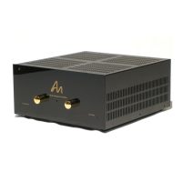
Well done – we have almost completed wiring of the
amplifier – One last thing to add is a ground lead from the
power supply to the chassis ground.
Connect this prepared cable from the chassis ground screw
behind the mains transformer and connect over to the
available P_GND on the power supply Board.
See the remaining two pictures for clarification...