15
ATUC-50IU
100
116
100
86
117
173
100
50
24
φ5
φ5
φ5
φ12
25
13.5
38
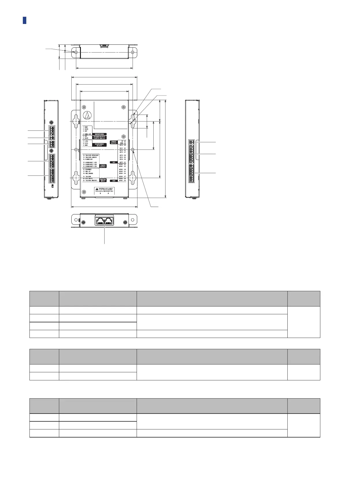
Because the IU is intended to be embedded in a table, etc., when it is used, the user interfaces, such as displays, operating terminals, and input/
output terminals, can be customized according to their usage environment.
Specifications for the interfaces are as follows.
Microphone input terminal
Pin
number
Signal name Explanation
Terminal
color
1 GND Microphone input GND
Green
2 COLD
Microphone input balance
Supplies a phantom power supply of +48 V (possible to toggle on/off)
3 HOT
4 RING LED For controlling ATUC-M LED
Speaker output terminal
Pin
number
Signal name Explanation
Terminal
color
5 HOT
Speaker output
1.4 W, 8 Ω (impedance over 4 Ω)
Green
6 COLD
• We recommend using a shielded wire for the speaker output terminal. The GND shield in this case is connected to the GND pin (9).
Headphone output terminal
Pin
number
Signal name Explanation
Terminal
color
7 L ch
Headphone output
15 mW 32 Ω
Green8 R ch
9 GND Headphone output GND
 Loading...