44
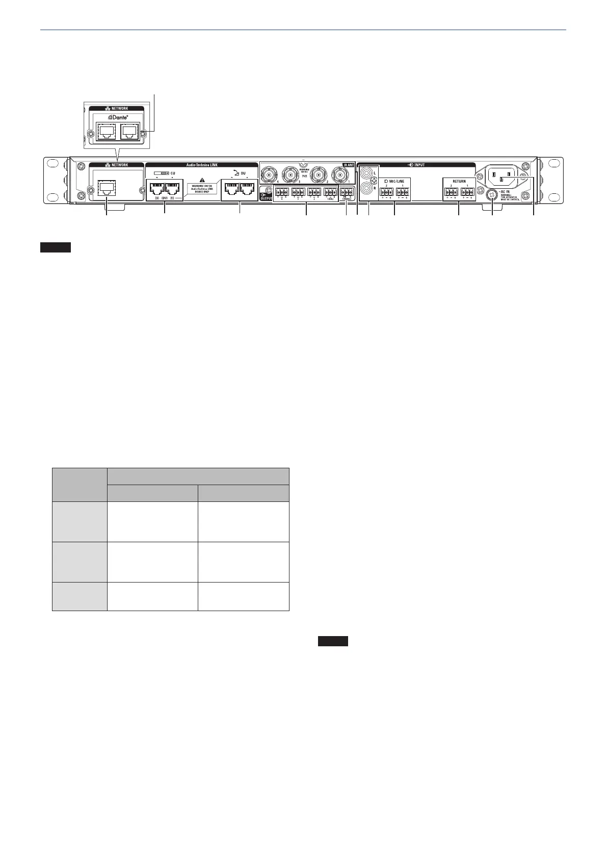
Rear panel
* The serial number label is located on the top panel.
⑬ ㉔
⑮
⑭
⑯
⑰ ⑳⑱ ⑲ ㉑
㉒ ㉓
NOTICE
• Refer also to the instruction manuals supplied with the
external devices.
• Be careful NOT to connect the Ethernet cable from your
network device to the CU LINK terminal or DU CHAIN
terminal. This can cause damage to the connected device.
NETWORK terminal
• RJ-45
• Use for connecting to a local area network when controlling
from an external device via the Web Remote Control or IP
remote function.
Dante network terminals
(ATUC-IRCUDAN)
• RJ-45
• Connect to Dante audio network, or use for connections when
controlling externally through Web Remote/IP remote.
• The primary terminal and secondary terminal mode settings are
shown in the following table.
Mode
Connected device
Primary Secondary
Switched
Dante network
Web Remote/external
control
Dante network
Web Remote/external
control
Redundant
Dante network (primary)
Web Remote/external
control
Dante network
(secondary)
Split
(Default)
Web Remote/external
control
Dante network
CU LINK A/B terminals, DU CHAIN C/D terminals
• RJ-45
• Use for cascading multiple CUs.
• You can also configure these terminals as DU/IU/INT
terminals.
DU CHAIN A/B terminals
• RJ-45
• Use for connecting DU/IU/INT. You can daisy-chain multiple
DU/IU/INTs as well as connect multiple DU/IU/INTs in a
ring using the A/B terminals.
Analog output (balanced) terminals: OUTPUT 1-4 (BAL)
• Euroblock
• Pin arrangement: “+” Hot/“–” Cold/“G” GND
Analog output (unbalanced) terminals: OUTPUT1
(UNBAL)
• Euroblock
• Pin arrangement: “SIG” Signal (2 systems)/“G” GND
Infrared input/output terminals: IR ANT
Use for connecting ATUC-IRA.
• BNC connector
Analog input (unbalanced) terminals: INPUT (AUX)
• RCA
Analog input (balanced) terminals: INPUT (MIC/LINE
1-2)
• Euroblock
• Pin arrangement: “+” Hot (supports phantom power)/“–” Cold
(supports phantom power)/“G” GND
• The input type can be switched between MIC and LINE
Analog input (balanced) terminal: INPUT
(INTERPRETATION RETURN 1-2)
• Euroblock
• Pin arrangement: “+” Hot/“–” Cold/“G” GND
• Inputs audio signals from simultaneous interpretation system
Ground screw
Since the supplied AC power cord has a three-pronged plug, as
long as your AC power wall outlet is grounded properly, the CU
will also be grounded properly.
AC inlet (AC IN)
Connect the supplied AC power cord.
NOTICE
• Do not plug in the AC power cord until all other
connections, including CU extension and DU/IU/INT/
IRDUs, have been completed.
• Be sure that the CU is securely grounded to a single
ground point. Grounding to multiple ground points can
cause ground loops, resulting in noise generation such as
a humming noise.
 Loading...