MediaPack SIP User’s Manual 3. Installing the MediaPack
Version 4.6 33 June 2005
3.1.3 Cabling the MP-1xx
Verify that you have the cables listed under column ‘Cable’ in Table 3-1 before beginning to cable
the MP-1xx according to the column ‘Cabling Procedure’. For detailed information on the MP-1xx
rear panel connectors, refer to Section
2.1.2 on page 25.
Table
3-1: Cables and Cabling Procedure
Cable Cabling Procedure
RJ-45 Ethernet
cable
Connect the Ethernet connection on the MP-1xx directly to the network using a standard RJ-45
Ethernet cable. For connector’s pinout refer to Figure 3-5 below.
Note that when assigning an IP address to the MP-1xx using HTTP (under step 1 in Section
4.2.1), you may be required to disconnect this cable and re-cable it differently.
Connect the RJ-11 connectors on the rear panel of the MP-10x/FXS to
fax machine, modem, or phones (refer to Figure
3-6).
Connect RJ-11 connectors on the MP-10x/FXO rear panel to telephone
exchange analog lines or PBX extensions (Figure
3-6).
Ensure that FXS &
FXO are connected to
the correct devices,
otherwise damage can
occur.
RJ-11 two-wire
telephone cords
MP-124/FXS ports are usually distributed using an MDF Adaptor Block (special order option).
Refer to Figure
3-8 for details.
Lifeline cable
For detailed information on setting up the Lifeline, refer to the procedure under Section 3.1.3.2 on
page 35.
50-pin Telco cable
(MP-124 devices
only).
An Octopus cable
is not included
with the MP-124
package.
Refer to the MP-124 Safety Notice below.
1. Wire the 50-pin Telco connectors according to the pinout in Figure 3-7 on page 34, and
Figure 3-8 on page 34.
2. Attach each pair of wires from a 25-pair Octopus cable to its corresponding socket on the
MDF Adaptor Block’s rear.
3. Connect the wire-pairs at the other end of the cable to a male 50-pin Telco connector.
4. Insert and fasten this connector to the female 50-pin Telco connector on the MP-124 rear
panel (labeled Analog Lines 1-24).
5. Connect the telephone lines from the Adaptor Block to a fax machine, modem, or telephones
by inserting each RJ-11 connector on the 2-wire line cords of the POTS phones into the RJ-
11 sockets on the front of an MDF Adaptor Block as shown in
Figure 3-8 on page 34.
RS-232 serial
cable
For detailed information on connecting the MP-1xx RS-232 port to your PC, refer to Section
3.1.3.1 on page 35.
Protective
earthing strap
Connect an earthed strap to the chassis protective earthing screw and fasten it securely according
to the safety standards.
AC Power cable
Connect the MP-1xx power socket to the mains.
MP-124 Safety Notice
To protect against electrical shock and fire, use a 26 AWG min wire to connect analog
FXS lines to the 50-pin Telco connector.
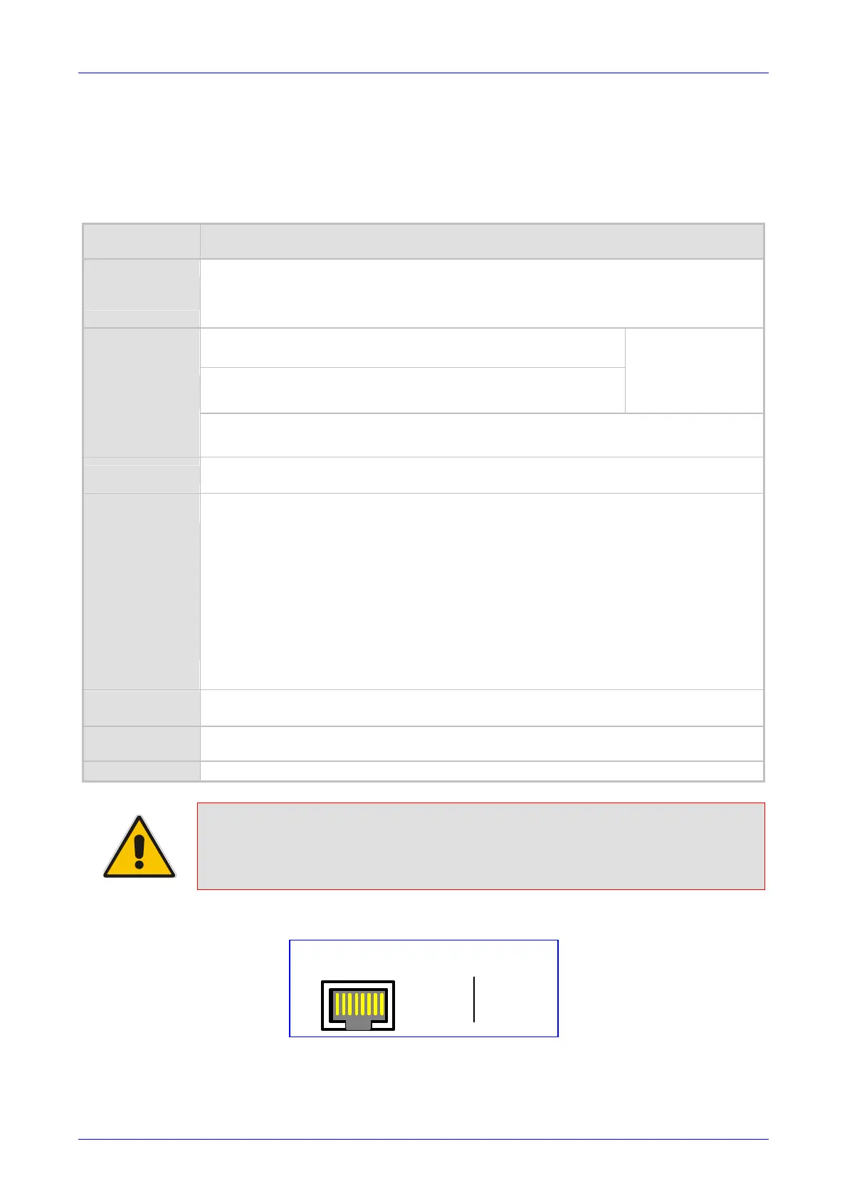
Figure 3-5: RJ-45 Ethernet Connector Pinout
1 2 3 4 5 6 7 8
RJ-45 Connector and Pinout
4, 5, 7, 8
not
connected
1 - Tx+
2 - Tx-
3 - Rx+
6 - Rx-

 Loading...