5.3.3. Output drive types B/C/D and E
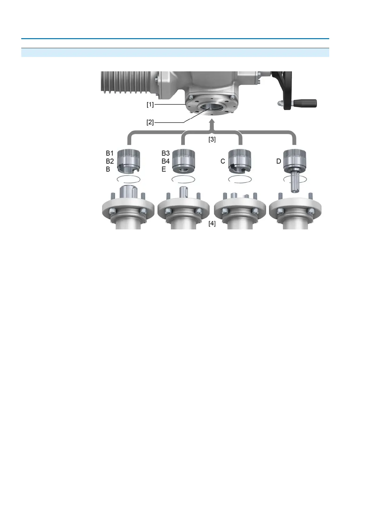
Figure 18: Mounting principle
[1] Flange multi-turn actuator (e.g. F07)
[2] Hollow shaft
[3] Output drive sleeve (illustration examples)
[4] Gearbox/valve shaft
Short description
Connection between hollow shaft and valve or gearbox via output drive sleeve fixed
to the hollow shaft of the multi-turn actuator via retaining ring.
When exchanging the output drive sleeve, later retrofitting to a different output drive
type is possible
●
Output drive type B/E:
Output drive sleeve with bore according to DIN 3210
●
Output drive types B1/B3:
Output drive sleeve with bore according to EN ISO 5210
●
Output drive types B2/B4:
Output drive sleeve with bore according to customer order
B4 including special bores like bores without keyway, square bore, hexagon
bore, internal splines
●
Output drive type C:
Output drive sleeve with dog coupling according to EN ISO 5210 or DIN 3338
●
Output drive type D:
Shaft end with key according to EN ISO 5210 or DIN 3210
Information
Spigot at valve flanges should be loose fit.
22
SAEx 07.2 – SAEx 16.2/SAREx 07.2 – SAREx 16.2 Control unit - electromechanical
Assembly ACExC 01.2 Intrusive Modbus RTU