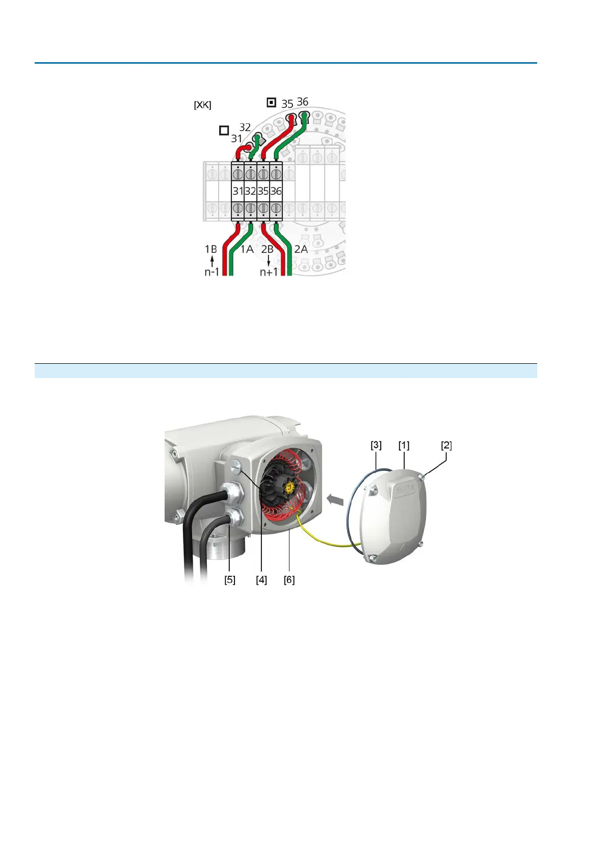
Figure 35: Terminal assignment of support terminals (2-channel)
[XK] Terminal assignment according to wiring diagram (customer connection)
□
Channel 1
▣
Channel 2
n–1 Fieldbus cable from previous device (input via channel 1)
n+1 Fieldbus cable to next device (input via channel 2)
6.3.4. Terminal compartment: close
Figure 36: Close terminal compartment
[1] Cover (illustration shows KT version in type of protection Ex e)
[2] Screws for cover
[3] O-ring
[4] Blanking plug
[5] Cable gland
[6] KT-Ex e connection frame
Procedure
1. Clean sealing faces of cover [1] and connection frame [6].
2. For design in flameproof enclosure (Ex d): Preserve joint surfaces with an acid-
free corrosion protection agent.
3. Check whether O-ring [3] is in good condition, replace if damaged.
4. Apply a thin film of non-acidic grease (e.g. petroleum jelly) to the O-ring and
insert it correctly.
36
SAEx 07.2 – SAEx 16.2/SAREx 07.2 – SAREx 16.2 Control unit - electromechanical
Electrical connection ACExC 01.2 Intrusive Modbus RTU