Technical data
Table 23:
KP/KPH electrical connection
Control contactsPower contacts
38 pins/sockets + protective earth con-
ductor (PE)
3 + protective earth conduct-
or (PE)
No. of contacts max.
1 to 24, 31 to 40, 47 to 50, PE
U1, V1, W1, (PE)
Designations
250 V525 VConnection voltage max.
10 A25 ARated current max.
Screw connectionScrew connectionType of customer connection
1.5 mm
2
6 mm
2
Connection diameter max.
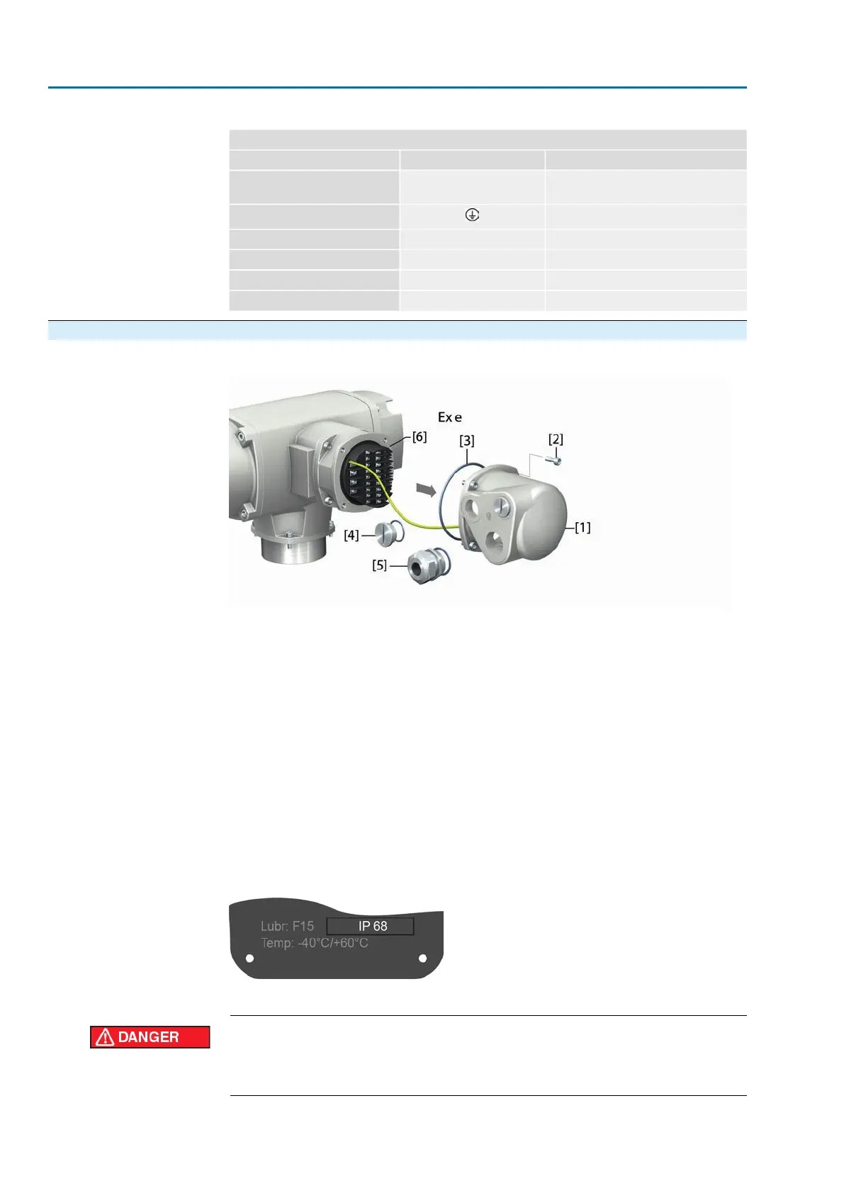
6.4.1. Terminal compartment: open
Figure 38:
[1] Cover (figure shows KP version)
[2] Screws for cover
[3] O-ring
[4] Blanking plugs
[5] Cable gland (example)
[6] Flameproof frame
Type of protection
The terminal compartment is designed in protection type Ex e (increased safety).
The flameproof interior of the connected device remains closed when removing the
cover [1].
Cable glands
When selecting cable glands observe type of protection (with Ex e approval) and
enclosure protection IP (refer to name plate).
The enclosure protection IP… stated on the name plate is only ensured if suitable
cable glands are used.
Figure 39: Name plate, example with enclosure protection IP68
For shielded cables: Use EMC cable glands.
Electric shock due to presence of hazardous voltage!
Failure to observe this warning results in death or serious injury.
→
Disconnect device from the mains before opening.
38
SAEx 07.2 – SAEx 16.2/SAREx 07.2 – SAREx 16.2 Control unit - electromechanical
Electrical connection ACExC 01.2 Intrusive Modbus RTU