11. For versions with terminal compartment in type of protection Ex d (flameproof
enclosure): Fasten grub screws [6] (tightening torque approx. 10 Nm).
Information: The flameproof enclosure is only guaranteed provided the grub
screws are fastened [6].
12. Fit cover [1] and fasten screws [2] evenly crosswise.
13.2.2. Disconnection from the mains with KP/KPH and KES electrical connection
Ignition of potentially explosive atmospheres caused by sparks.
Risk of death or serious injury.
→
Before opening the flameproof enclosure, ensure absence of gas and voltage.
→
Handle cover and housing parts with care.
→
Joint surfaces must not be damaged or soiled in any way.
→
Do not jam cover during fitting.
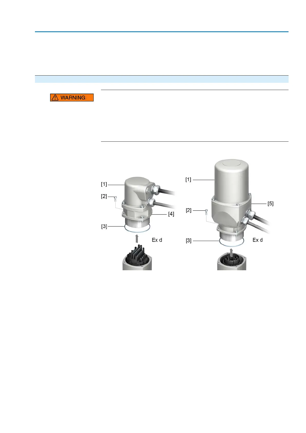
Figure 97: KP/KPH and KES electrical connection
[1] Cover
[2] Screws for housing
[3] O-ring
[4] Plug-in frame (KP/KPH)
[5] Connection frame (KES)
Removing the plug:
1. Loosen the screws [2].
2. Remove electrical connection.
➥
Cover [1] and plug-in type frame [4] or connection frame [5] remain together.
3. Seal open plug/socket connection, e.g. using AUMA protection cover and
parking frame.
Fitting the plug/socket
connector:
4. Clean sealing faces of plug/socket connector and housing.
5. Preserve joint surfaces with an acid-free corrosion protection agent.
6. Check whether O-ring [3] is in good condition, replace if damaged.
7. Apply a thin film of non-acidic grease (e.g. petroleum jelly) to the O-ring and
insert it correctly.
8. Replace electrical connection and fasten screws evenly crosswise.
91
SAEx 07.2 – SAEx 16.2/SAREx 07.2 – SAREx 16.2 Control unit - electromechanical
ACExC 01.2 Intrusive Modbus RTU Servicing and maintenance