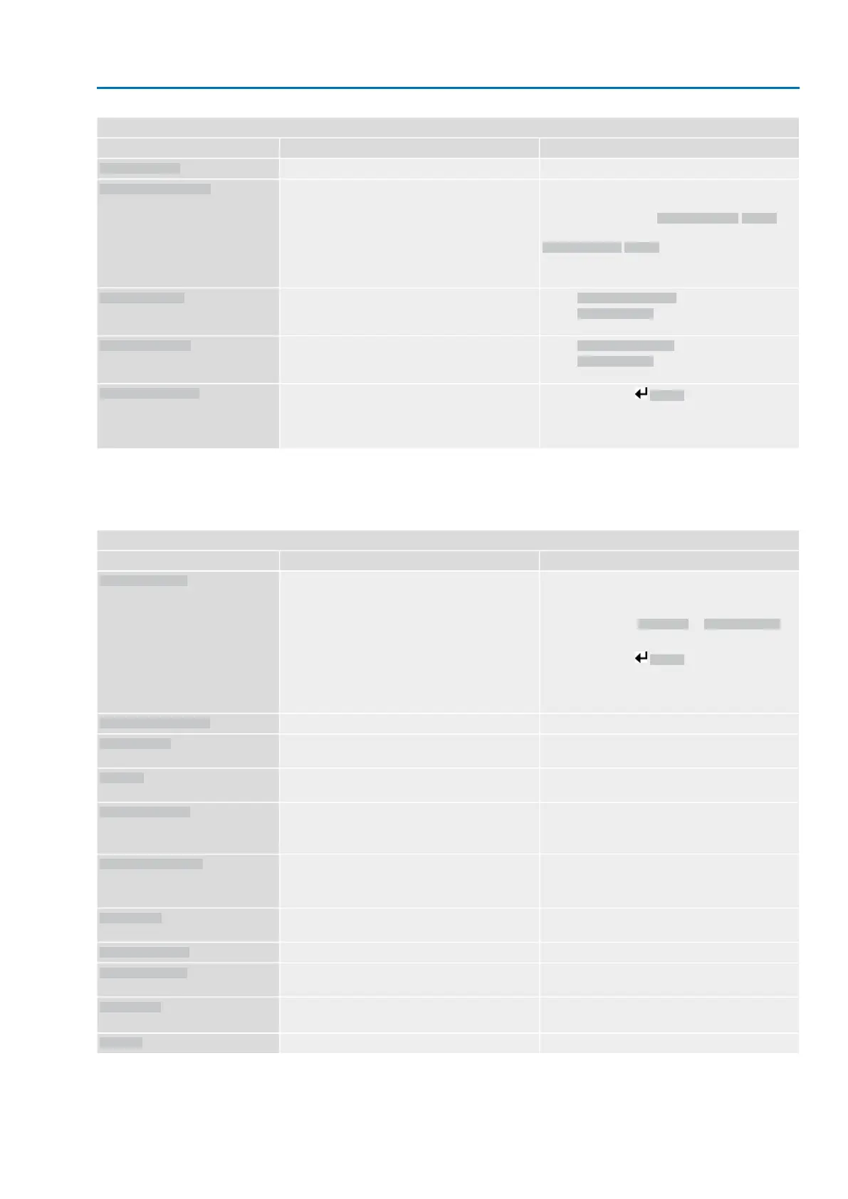
Faults and Failure
RemedyDescription/causeIndication on display
Check wiring.Loss of signal analogue input 2
Wrn input AIN 2
Check operation command control.
For 3-phase AC current mains, activate phase
monitoring (parameter Adapt rotary dir. M0171).
Check device configuration setting (parameter
Closing rotation M0176).
To delete the fault indication: Disconnect actuator
controls from the mains and perform reboot.
Contrary to the configured direction of rotation and
the active operation command, the motor turns into
the wrong direction.
Incorrect rotary direct.
Check DMF trip torque OP parameter.
Check DMF fault level parameter.
The torque in direction OPEN, measured at the
output drive shaft using the torque measurement
flange, is too high.
DMF fault OPEN
2)
Check DMF trip torque CL parameter.
Check DMF fault level parameter.
The torque in direction CLOSE, measured at the
output drive shaft using the torque measurement
flange, is too high.
DMF fault CLOSE
2)
Press push button Details to display a list of indi-
vidual indications.
For a description of the individual signals, refer to
Manual (Operation and setting).
Collective signal 25:
FQM collective fault
3)
For lift plug valve product variant1)
For actuators equipped with torque measurement flange (DMF)2)
For actuators equipped with fail safe unit3)
Table 40:
Not ready REMOTE and Function check (collective signal 04)
RemedyDescription/causeIndication on display
●
Check operation commands (reset/clear all op-
eration commands and send one operation
command only).
●
Set parameter Positioner to Function active.
●
Check setpoint.
Press push button Details to display a list of indi-
vidual indications.
For a description of the individual signals, refer to
Manual (Operation and setting).
Collective signal 13:
Possible causes:
●
Several operation commands (e.g. OPEN and
CLOSE simultaneously, or OPEN and SET-
POINT operation simultaneously)
●
A setpoint is present and the positioner is not
active
Wrong oper. cmd
Set selector switch to position REMOTE.Selector switch is not in position REMOTE.
Sel. sw. not REMOTE
Exit service software.Operation via service interface (Bluetooth) and
AUMA CDT service software.
Service active
Check setting and status of function <Local controls
enable>.
Actuator is in operation mode Disabled.
Disabled
●
Enable EMERGENCY stop switch.
●
Reset EMERGENCY stop state by means of
Reset command.
The EMERGENCY stop switch has been operated.
The motor control power supply (contactors or
thyristors) is disconnected.
EMCY stop active
●
Detect cause for EMERGENCY signal.
●
Verify failure source.
●
Apply +24 V DC at EMERGENCY input.
Operation mode EMERGENCY is active (EMER-
GENCY signal was sent).
0 V are applied at the EMERGENCY input.
EMCY behav. active
Check I/O interface.The actuator is controlled via the I/O interface (par-
allel).
I/O interface
Start motor operation.Manual operation is activated.
Handwheel active
Verify master configurationFieldbus connection available, however no process
data transmission by the master.
FailState fieldbus
Release push button STOP.A local STOP is active.
Push button STOP of local controls is operated.
Local STOP
Check interlock signal.An interlock is active.
Interlock
85
SAEx 07.2 – SAEx 16.2/SAREx 07.2 – SAREx 16.2 Control unit - electromechanical
ACExC 01.2 Intrusive Modbus RTU Corrective action