6. Electrical connection
6.1. Overview of AUMA electrical connections
The section below provides an overview of the different electrical connections
described in the chapters to follow.
Table 14: Versions of the AUMA plug/socket connector
For description
and assembly
refer to chapter
PropertiesFigureElectrical con-
nection
➭ page 29, SJ
electrical connec-
tion (AUMA
plug/socket con-
nector)
Plug/socket connector with enlarged
terminal compartment
SJ
6.2. Basic information
Electric shock due to presence of hazardous voltage!
Risk of death or serious injury!
→
The electrical connection must be carried out exclusively by suitably qualified
personnel.
→
Prior to connection, observe basic information contained in this chapter.
→
After connection but prior to applying the voltage, observe the <Commissioning>
and <Test run> chapters.
Wiring diagram/terminal
plan
The pertaining wiring diagram/terminal plan (in German or English) is attached to
the device in a weather-proof bag, together with these operation instructions. It can
also be requested from AUMA (state order number, refer to name plate) or
downloaded directly from the Internet (http://www.auma.com).
Permissible networks
(supply networks)
The actuators are suitable for use in TN and TT networks with directly grounded star
point for nominal voltages up to maximum 690 V AC. Use in IT network is permissible
for nominal voltages up to maximum 600 V AC. For IT network, a suitable, approved
insulation monitor measuring the pulse code is required.
Current type, mains
voltage, mains fre-
quency
Type of current, mains voltage and mains frequency must match the data on the
actuator controls and motor name plates. Also refer to chapter <Identification>/<Name
plate>.
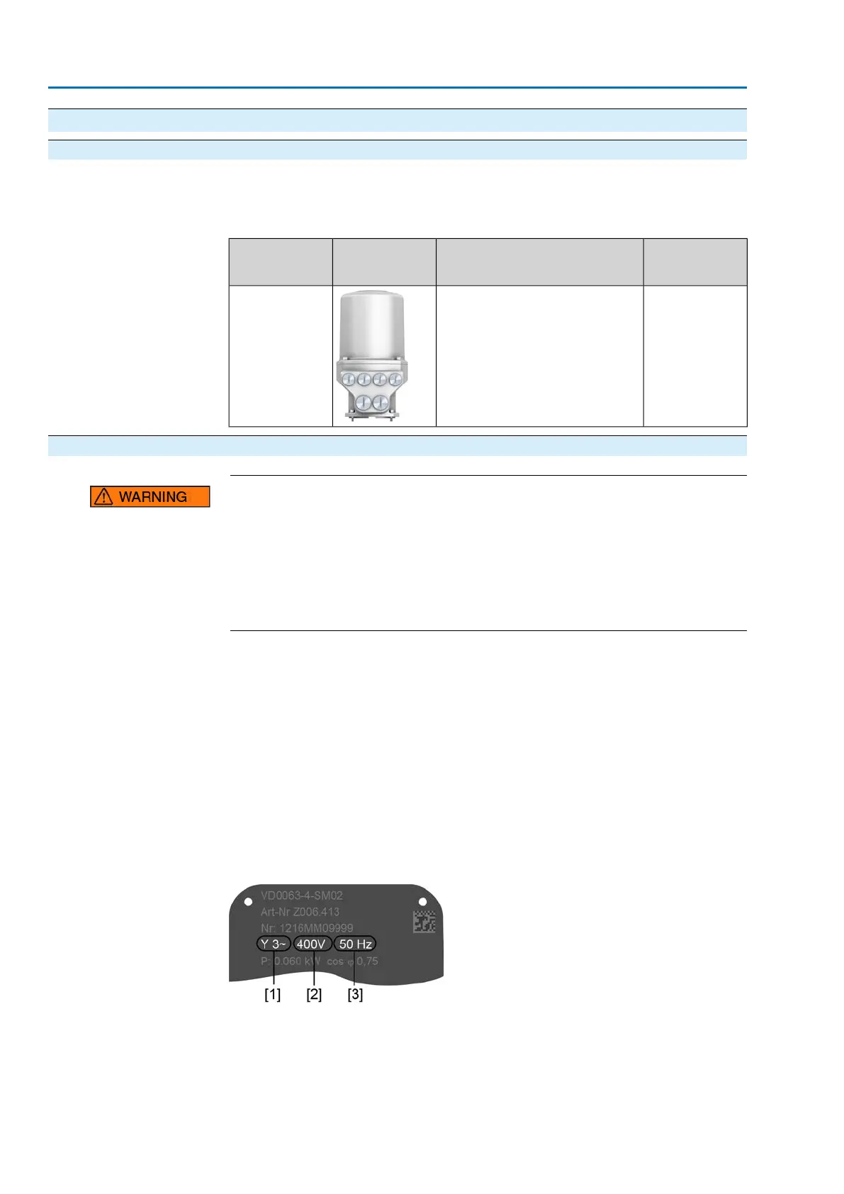
Figure 22: Motor name plate (example)
[1] Type of current
[2] Mains voltage
[3] Mains frequency
26
SA 07.2 – SA 16.2 / SAR 07.2 – SAR 16.2 Control unit: electronic (MWG)
Electrical connection AC 01.2 Non-Intrusive DeviceNet