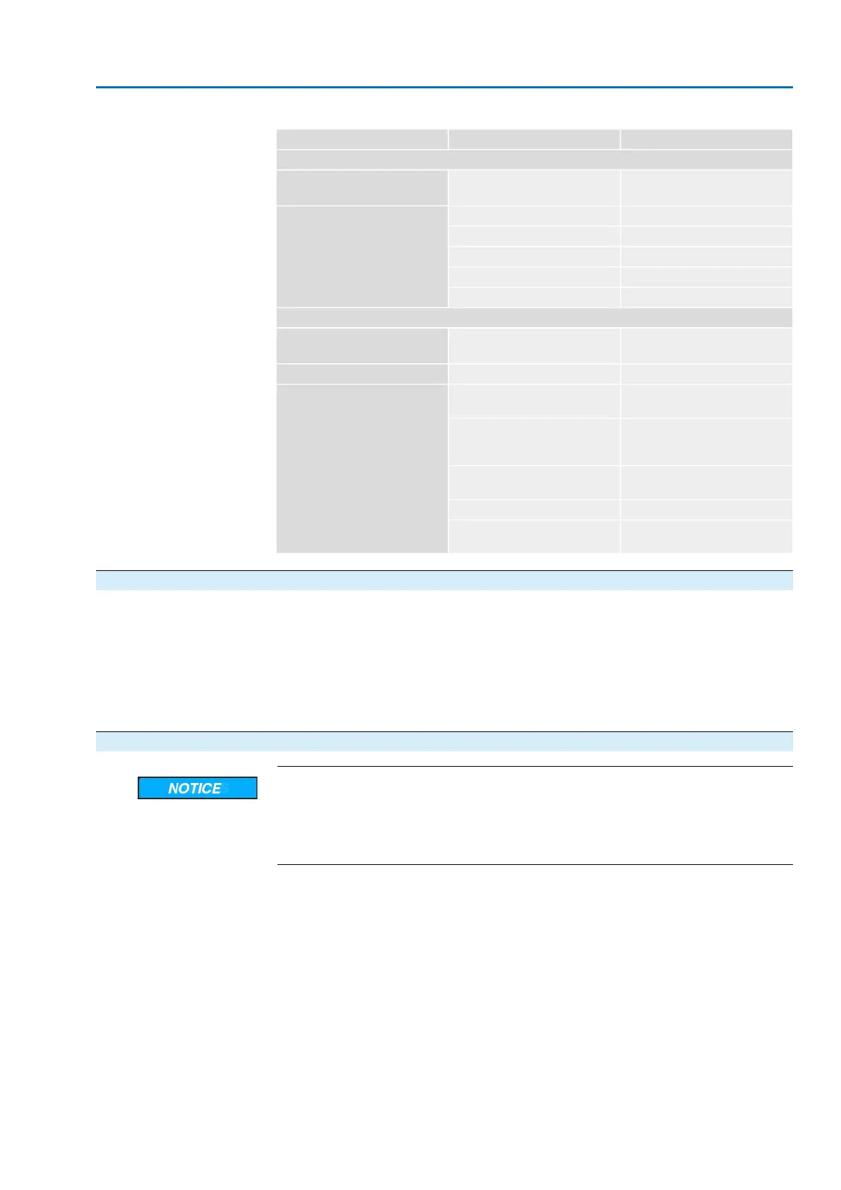
Table 29: Signification of LED
SignificationColourLED
DeviceNet
Supply voltage availableGreenBus Power
(DeviceNet supply voltage)
Gateway connected to masterIlluminated in greenBus State
(DeviceNet interface state)
No connection to masterBlinking in green
Remediable error (e.g. timeout)Blinking in red
Severe error (e.g. double MAC-ID)Illuminated in red
Communication errorBlinking in red/green
Application
Supply voltage availableGreenPower/State
(supply voltage of serial interface)
General gateway error (if blinking)Green1 / 2 / 4 / 8
Data exchange with serial inter-
face is active
Illuminated in greenState
Connection o.k.; however no per-
manent data exchange with serial
interface
Blinking in green
Gateway is in configuration or test
mode
Blinking in red
General gateway errorIlluminated in red
Still no data exchange since power
on
Blinking in red/green
10.5. Test run
Only perform test run only once all settings previously described have been
performed.
The direction of rotation can be checked at the position indicator if available. (Chapter
<Direction of rotation at mechanical position indicator: check>)
The direction of rotation must be checked at the hollow shaft/stem if no mechanical
position indicator is available. (Chapter <Direction of rotation at hollow shaft/stem:
check>)
10.5.1. Direction of rotation at mechanical position indicator: check
Valve damage due to incorrect direction of rotation!
→
If the direction of rotation is wrong, switch off immediately (press STOP).
→
Eliminate cause, i.e. correct phase sequence for cable set wall bracket.
→
Repeat test run.
Information Switch off before reaching the end position.
1. Move actuator manually to intermediate position or to sufficient distance from
end position.
71
SA 07.2 – SA 16.2 / SAR 07.2 – SAR 16.2 Control unit: electronic (MWG)
AC 01.2 Non-Intrusive DeviceNet Commissioning (basic settings)