10.4. Settings at the DeviceNet gateway
10.4.1. Fieldbus address and baud rate setting
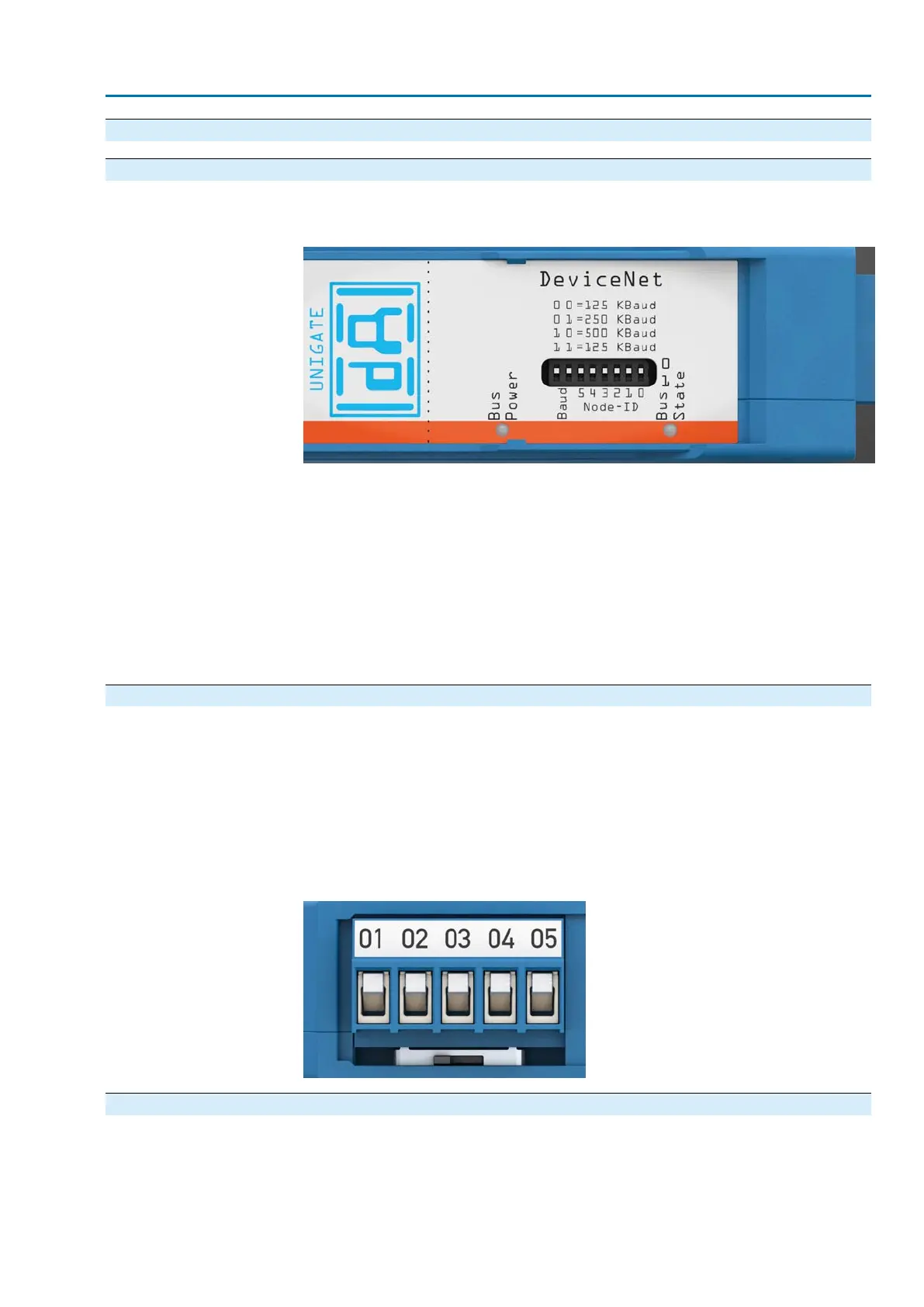
Fieldbus address and baud rate can be set via the DIP switch at the gateway.
Figure 68: Gateway range “DeviceNet”
The DIP switches may be either set to 0 or to 1. Both left DIP switches are used to
set the baud rate:
00 = 125 KBaud
01 = 250 KBaud
10 = 500 KBaud
11 = 125 KBaud
The six right DIP switches are used to set the DeviceNet Node ID. The setting is
performed as binary from 0 (all DIP switches in position 0) to 63 (all DIP switches in
position 1).
10.4.2. Termination
A bus termination is required if the actuator is the first or the last fieldbus device
within the fieldbus segment.This can be made either by bus termination resistor
within the connector or by activating the resistor (220 Ohm) integrated within the
gateway.
For this, push the sliding switch at the side of the gateway to On position. In all other
cases, the sliding switch remains in Off position. Refer to the sticker placed on the
gateway to identify which sliding switch positions correspond respectively to “On” or
“Off” position.
Figure 69: Termination of sliding switch
10.4.3. Input and output data
The rotating coding switches S4 and S5 are used to select the desired representation
of the input and output data of the DeviceNet interface.
61
SA 07.2 – SA 16.2 / SAR 07.2 – SAR 16.2 Control unit: electronic (MWG)
AC 01.2 Non-Intrusive DeviceNet Commissioning (basic settings)