Home
AUMA
Controller
SAR 07.2
AUMA SAR 07.2 User Manual
4
of 1
of 1 rating
108 pages
Give review
Manual
Specs
To Next Page
To Next Page
To Previous Page
To Previous Page
Loading...
Consumed Emulation / Data Description
S5
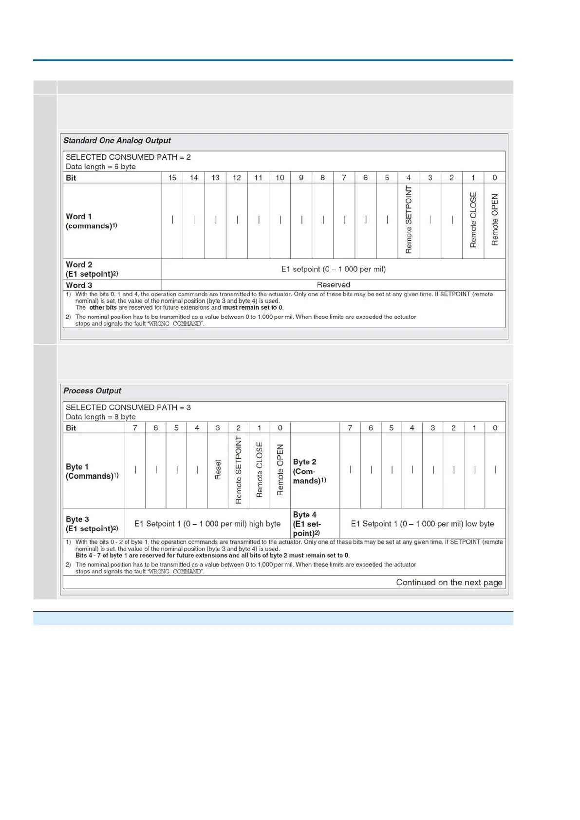
AC01.1 Standard One Analog Output
Selected Consumed P
ath = 2
Data length = 6 bytes
2
AC01.1 Process Output
Selected Consumed P
ath = 3
Data length = 8 bytes
3
10.4.4.
LED
The De
viceNet gatewa
y is equipped with 8 LEDs (refer to illustrations in this chapter).
70
SA 07.2
–
SA 16.2 / SAR 07.2
–
SAR 16.2 Control unit:
electronic (MWG)
Commissioning (basic settings)
A
C 01.2 Non-Intrusive De
viceNet
69
71
Table of Contents
Table of Contents
2
Safety Instructions
5
Prerequisites for the Safe Handling of the Product
5
Range of Application
5
Warnings and Notes
6
References and Symbols
6
Short Description
7
Name Plate
9
Transport and Storage
13
Transport
13
Storage
15
Assembly
17
Mounting Position
17
Handwheel Fitting
17
Mount Actuator to Valve
17
Overview of Output Drive Types
18
Output Drive Type a
18
5.3.2.1. Multi-Turn Actuator with Output Drive Type A: Mount
19
5.3.2.2. Stem Nut for Output Drive Type A: Finish Machining
21
Output Drive Types B/C/D and E
22
5.3.3.1. Multi-Turn Actuator with Output Drive Type B: Mount
23
Accessories for Assembly
24
Stem Protection Tube for Rising Valve Stem
24
Mounting Positions of Local Controls
25
Mounting Positions: Modify
25
Electrical Connection
26
Overview of AUMA Electrical Connections
26
Basic Information
26
SJ Electrical Connection (AUMA Plug/Socket Connector)
29
Terminal Compartment (for Mains Connection): Open
30
Cable Connection
31
Terminal Compartment (for Mains Connection): Close
32
Fieldbus Terminal Compartment: Open
33
Devicenet Cable: Connect
33
Fieldbus Terminal Compartment: Close
34
Accessories for Electrical Connection
35
Actuator Controls on Wall Bracket
35
Parking Frame
36
DS Intermediate Frame for Double Sealing
36
External Earth Connection
37
Operation
38
Manual Operation
38
Manual Valve Operation
38
Motor Operation
39
Operating the Actuator from Local Controls
39
Actuator Operation from Remote
40
Menu Navigation Via Push Buttons (for Settings and Indications)
40
Menu Layout and Navigation
41
User Level, Password
42
Password Entry
43
Password Change
43
Timeout for Incorrect Password Entry
44
Language in the Display
44
Language Change
44
Indications
46
Indications During Commissioning
46
Indications in the Display
46
Feedback Signals from Actuator and Valve
47
Status Indications According to AUMA Classification
49
Status Indications According to NAMUR Recommendation
50
Indication Lights of Local Controls
52
Optional Indications
53
Mechanical Position Indication Via Indicator Mark (Not Self-Adjusting)
53
Mechanical Position Indication (Self-Adjusting)
53
Signals (Output Signals)
54
Signals Via Devicenet
54
Status Signals Via Output Contacts (Digital Outputs)
54
Assignment of Outputs
54
Coding the Outputs
54
Analogue Signals (Analogue Outputs)
54
Commissioning (Basic Settings)
56
Type of Seating: Set
56
Torque Switching: Set
57
Limit Switching: Set
59
Settings at the Devicenet Gateway
61
Fieldbus Address and Baud Rate Setting
61
Termination
61
Input and Output Data
61
Led
70
Test Run
71
Direction of Rotation at Mechanical Position Indicator: Check
71
Direction of Rotation at Hollow Shaft/Stem: Check
73
Limit Switching: Check
73
Commissioning (Settings/Options in the Actuator)
75
Switch Compartment: Open/Close
75
Mechanical Position Indicator (Self-Adjusting)
76
Mechanical Position Indicator: Set
76
Gear Stage of the Reduction Gearing: Test/Set
77
Mechanical Position Indication Via Indicator Mark (Not Self-Adjusting)
78
Mechanical Position Indicator: Set
78
Gear Stage of the Reduction Gearing: Test/Set
78
Corrective Action
81
Faults During Commissioning
81
Fault Indications and Warning Indications
81
Fuses
85
Fuses Within the Actuator Controls
85
Fuse Replacement
86
Replace Fuses
86
Test/Replace Fuses
86
Motor Protection (Thermal Monitoring)
87
Servicing and Maintenance
88
Preventive Measures for Servicing and Safe Operation
88
Maintenance
89
Disposal and Recycling
89
Technical Data
90
Technical Data Multi-Turn Actuators
90
Technical Data Actuator Controls
92
Tightening Torques for Screws
97
Spare Parts
99
Multi-Turn Actuators SA
99
Sa 16.2/Sar 07.2
99
Sar 16.2
99
AC 01.2 Actuator Controls with SJ Electrical Connection
101
Index
105
Other manuals for AUMA SAR 07.2
Operating Instructions
104 pages
Operation Instructions
100 pages
Manual
52 pages
Assembly Instructions
3 pages
4
Based on 1 rating
Ask a question
Give review
Questions and Answers:
Need help?
Do you have a question about the AUMA SAR 07.2 and is the answer not in the manual?
Ask a question
AUMA SAR 07.2 Specifications
General
Type of actuator
Multi-turn actuator
Protection class
IP68
Output speed
4 to 180 rpm
Ambient temperature
-25°C to +70°C
Housing material
Aluminum
Related product manuals
AUMA SAR 07.6
104 pages
AUMA SAR 07.5
80 pages
AUMA SAR 07.1 - SAR 30.1
60 pages
AUMA SAR 6
44 pages
AUMA SAR 12
44 pages
AUMA SAR 10.2
104 pages
AUMA SAR 14.6
104 pages
AUMA SAR 14.1
80 pages
AUMA SAR 14.5
80 pages
AUMA SAR 10.1
80 pages
AUMA SAR 16.2
108 pages
AUMA SA 48.1 SAR 25.1
92 pages