Figure 30: X3 customer connection
Table 21: Pin assignment X3 (5 pole screw-type plug/socket connector)
UseFunctionPin no.
DeviceNet power supplyV– (0 V DC)1
Data cable (dominant low)CAN_L2
Shield cableShield3
Data cable (dominant high)CAN_H4
DeviceNet power supplyV+ (24 V DC)5
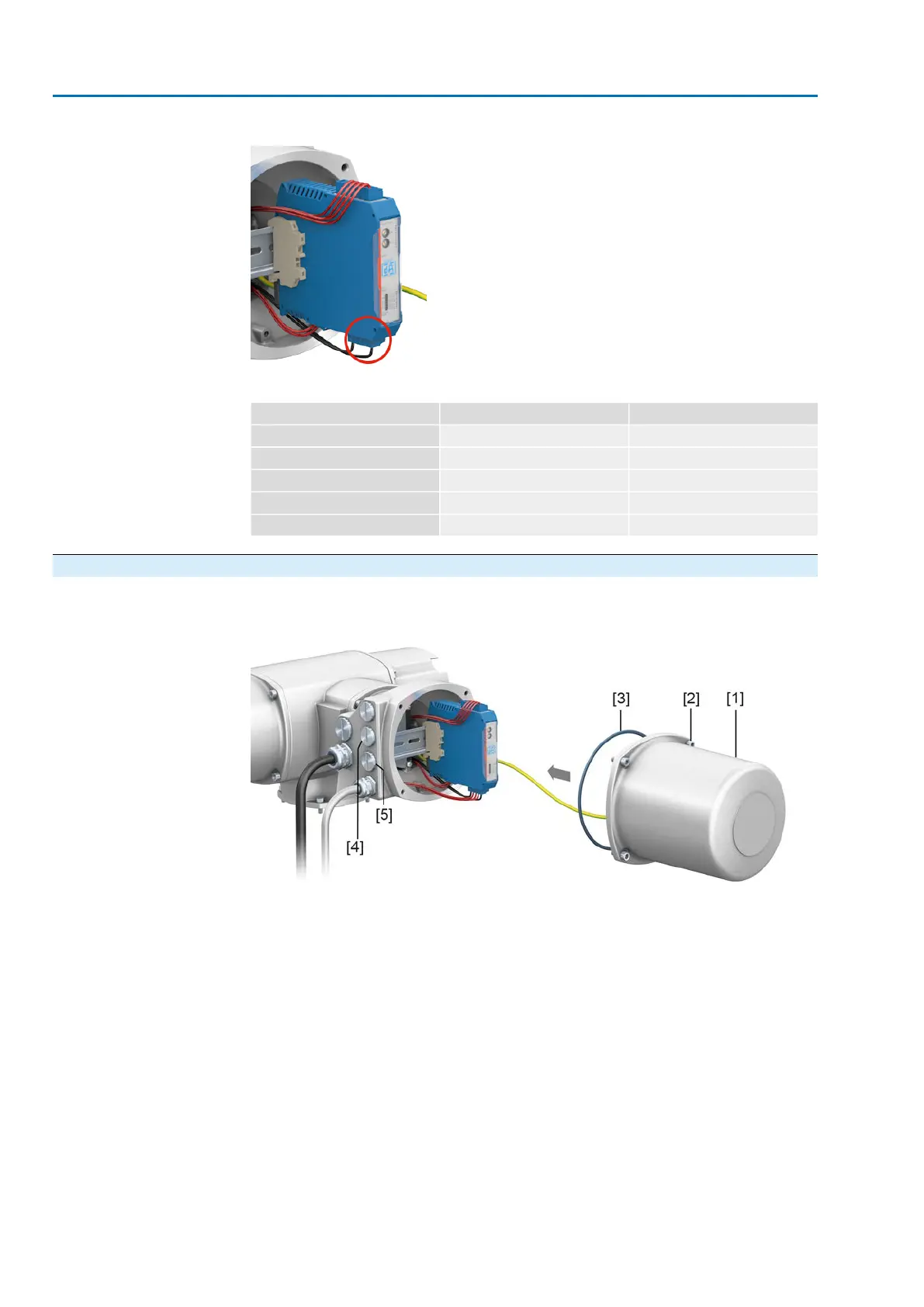
6.3.6. Fieldbus terminal compartment: close
Figure 31: Fieldbus terminal compartment: close
[1] Cover (fieldbus terminal compartment)
[2] Screws for cover
[3] O-ring
[4] Cable entries for fieldbus cables
[5] Blanking plug
1. Clean sealing faces of cover [1] and housing.
2. Apply a thin film of non-acidic grease (e.g. petroleum jelly) to the sealing faces.
3. Check whether O-ring [3] is in good condition, correctly insert O-ring.
4. Fit cover [1] and fasten screws [2] evenly crosswise.
5. Fasten cable glands and blanking plugs applying the specified torque to ensure
the required enclosure protection.
34
SA 07.2 – SA 16.2 / SAR 07.2 – SAR 16.2 Control unit: electronic (MWG)
Electrical connection AC 01.2 Non-Intrusive DeviceNet