Commissioning (optional equipment settings)
35
Technical data
Table17: EWG 01.1
Data 3-wire and 4-wire systems 2-wire system
Output current I
a
0 – 20 mA, 4 – 20 mA 4 – 20 mA
Power supply U
V
7)
24 V DC (18 – 32 V) 24 V DC (18 – 32 V)
Max. current consumption
LED off= 26 mA,
LED on = 27 mA
20 mA
Max. load R
B
600 Ω (U
V
– 12 V)/20 mA
Impact of power supply 0.1 %
Load influence 0.1 %
Temperature impact < 0.1 ‰/K
Ambient temperature
8)
–76 °F to 176 °F [–60 °C to +80 °C]
Setting elements The EWG is housed in the actuator switch compartment. The switch compartment
must be opened to perform any settings. Refer to Open switch compartment [}27].
All settings are made via the two push buttons [S1] and [S2].
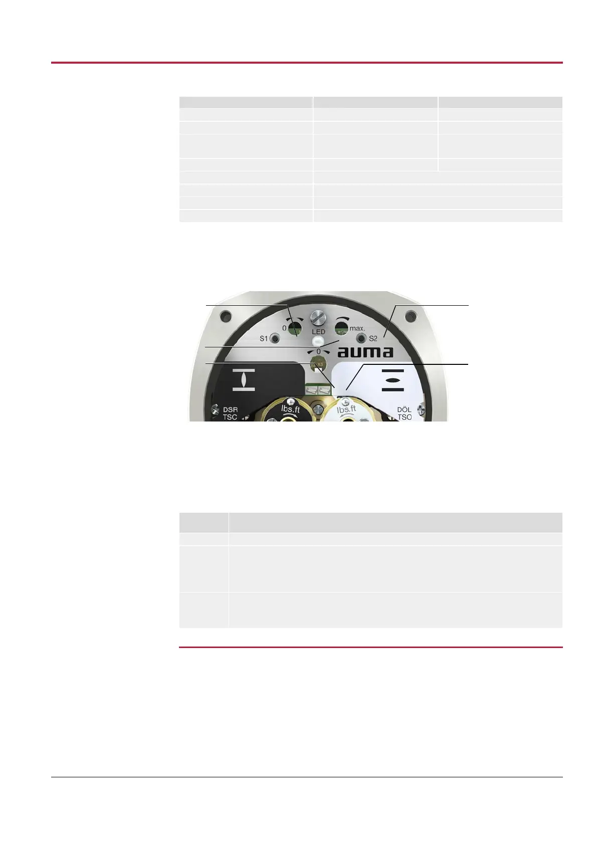
Figure35: View on control unit when switch compartment is open
[S1] Push button: Set 0/4 mA [S2] Push button: Set 20 mA
LED Optical aid for setting [1] Measuring point (+) 0/4 – 20 mA
[2] Measuring point (–) 0/4 – 20 mA
The output current (measuring range 0 – 20 mA) can be checked at measuring points
[1] and [2].
Table18: Short overview on push button functions
Push but-
tons
Function
[S1] + [S2] → press simultaneously for 5 s: Activate setting mode
[S1]
→ press in setting mode for 3 s: Set 4 mA
→ press in setting mode for 6 s: Set 0 mA (only possible for 3-/4-wire version)
→ press in operation for 3 s: Switch on/off LED end position signaling
→ touch in end position: Reduce current value by 0.02 mA
[S2]
→ press in setting mode for 3 s: Set 20 mA
→ press in operation for 3 s: Switch on/off LED end position signaling
→ touch in end position: Increase current value by 0.02 mA
11.3.1
Set measuring range
For measuring range setting, voltage must be applied at the position transmitter.
For output current verification, connect a test device for 0 – 20 mA to measurement
points (+/–) (for 2-wire systems, connecting a test device is required).
7) Power supply possible via: AC, AM actuator controls or external power supply
8) Depending on temperature range of the actuator: refer to name tag
 Loading...


