Electrical connection
20
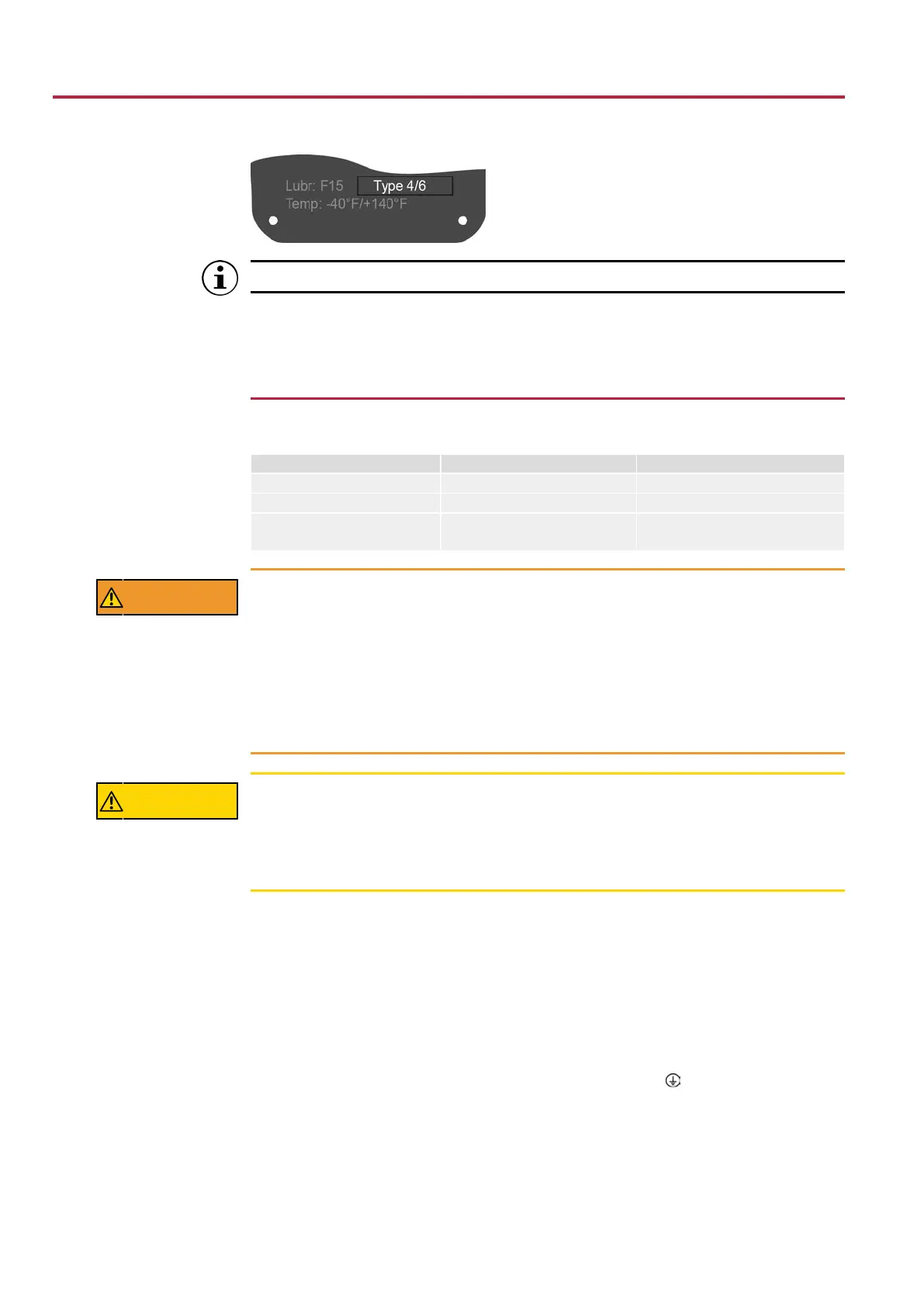
Figure15: Name tag, example with enclosure protection (NEMA) type
For shielded cables: Use EMC approved cable glands.
How to proceed 1. Loosen screws [2] and remove cover [1].
2. Insert cable glands suitable for connecting cables.
3. Seal unused cable entries with suitable plugs.
6.2.2
Cable connection
Table11: Terminal cross sections and terminal tightening torques
Designation Terminal cross sections Tightening torques
Power contacts (U, V, W) max. 10 mm² (flexible or solid) 1.1 – 1.3ft-lb [1.5 – 1.8Nm]
PE connection max. 10 mm² (flexible or solid) 2.2 – 2.9ft- lb [3.0 – 4.0Nm]
Control contacts (1 to 50)
max. 2,5 mm² (flexible) or
max. 4 mm² (solid)
0.4 – 0.6ft-lb [0.6 – 0.8Nm]
WARNING
In case of a fault: Hazardous voltage while protective earth conductor is
NOT connected!
Risk of electric shock
à Connect all protective earth conductors.
à Connect PE connection to external protective earth conductor of connecting ca-
bles.
à Start running the device only after having connected the protective earth conduc-
tor.
CAUTION
Without motor protection, impermissible high temperatures at the actua-
tor may occur: Ignition hazard, risk of explosion!
Risk of death, serious injury or motor damage. Our warranty for the motor will lapse if
the motor protection is not connected.
à Connect thermal switches to external controls.
How to proceed 1. Remove cable sheathing and insert the wires into the cable glands.
2. Fasten cable glands with the specified torque to ensure required enclosure protec-
tion. For shielded cables: Link the cable shield end via the cable gland to the
housing (grounding).
3. Strip wires.
4. Connect cables according to order-related wiring diagram.
5. WARNING!In case of a fault: Hazardous voltage while protective earth con-
ductor is NOT connected!
Firmly tighten protective earth to PE connection (symbol
).
 Loading...


