Commissioning (optional equipment settings)
33
11
Commissioning (optional equipment settings)
11.1
Potentiometer
The potentiometer is used as travel sensor and records the valve position.
Setting elements The potentiometer is housed in the actuator switch compartment. The switch compart-
ment must be opened to perform any settings. Refer to Open switch compartment
[}27].
Setting is made via potentiometer [1].
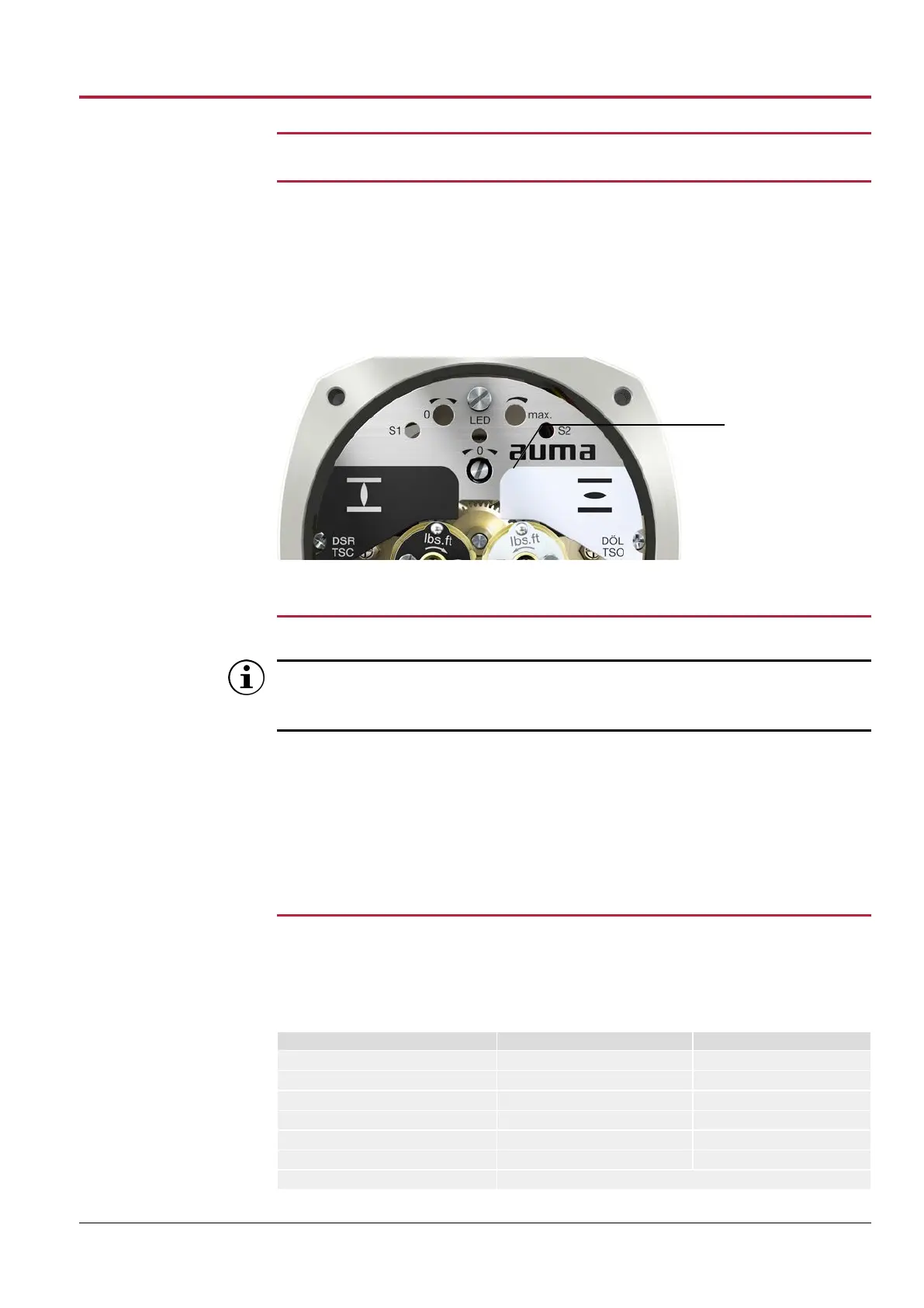
Figure33: View on control unit
[1] Potentiometer
11.1.1
Potentiometer setting
Due to the ratio of the reduction gearing, the complete resistance range/stroke
is not always covered. Therefore, external adjustment (setting potentiometer)
must be provided.
1. Move valve to end position CLOSED.
2. Turn potentiometer [1] clockwise to the stop.
ð End position CLOSED corresponds to 0 %
ð End position OPEN corresponds to 100 %
3. Turn potentiometer [1] slightly in opposite direction.
4. Perform fine-tuning of the zero point at external setting potentiometer (for remote
indication).
11.2
RWG electronic position transmitter
The RWG electronic position transmitter records the valve position. On the basis of
the actual position value measured by the potentiometer (travel sensor), it generates a
current signal between 0 – 20 mA or 4 – 20 mA.
Technical data
Table16: RWG 4020
Data 3-wire and 4-wire systems 2-wire system
Output current I
a
0 – 20 mA, 4 – 20 mA 4 – 20 mA
Power supply U
V
5)
24 V DC (18 – 32 V) 14 V DC + (I x R
B
), max. 30V
Max. current consumption 24 mA at 20 mA output current 20 mA
Max. load R
B
600 Ω (U
V
– 14 V)/20mA
Impact of power supply 0.1 %/V 0.1 %/V
Load influence 0.1 %/(0 – 600 Ω) 0.1 %/100 Ω
Temperature impact < 0.3 ‰/K
5) Power supply possible via: AC, AM actuator controls or external power supply
 Loading...


