Corrective actions
39
12
Corrective actions
12.1
Faults during operation/commissioning
Table20: Faults during operation and commissioning
Fault Description/cause Remedy
Mechanical position indicator cannot
be set.
Reduction gearing is not suitable for actuator
swing angle.
Set gear stage of the reduction gearing.
In spite of correct setting of mechani-
cal limit switching, actuator operates
into the valve or actuator end position.
The overrun was not considered when setting the
limit switches.
The overrun is generated by the inertia of both the
actuator and the valve and the delay time of the
actuator controls.
• Determine overrun: Overrun = travel covered
from switching off until complete standstill.
• Set limit switches again considering the over-
run. (Turn handwheel back by the amount of
the overrun)
No value can be measured at measur-
ing points of the RWG.
Current loop across RWG is open.
(Position feedback 0/4 – 20 mA is only possible if
the current loop is closed across the RWG.)
• Connect link across RWG to XK (terminals
23/24)
• Connect external load to XK, e.g. remote indi-
cation.
• Observe max. load R
B
.
Measuring range 0/4 – 20mA or maxi-
mum value 20mA at position transmit-
ter cannot be set or supplies an incor-
rect value.
Reduction gearing is not suitable for actuator
swing angle.
Set gear stage of the reduction gearing.
The measuring range 0/4 – 20mA at
EWG position transmitter cannot be
set.
The LED on the EWG either flashes in setting
mode a) single flash or b) triple flash:
a) EWG is not calibrated.
b) Magnet positions of EWG are not aligned.
Request AUMA Service.
Limit and/or torque switches do not
trip.
Switches are defective or switch setting is incor-
rect.
Check setting, if required, reset end positions.
Refer to Switch check [}39], replace switches if
required.
Handwheel rotates on the shaft with-
out transmitting torque.
Actuator in version with overload protection for
manual operation: Shear pin rupture due to exces-
sive torque at handwheel.
Dismount handwheel. Replace overload protection
and remount handwheel.
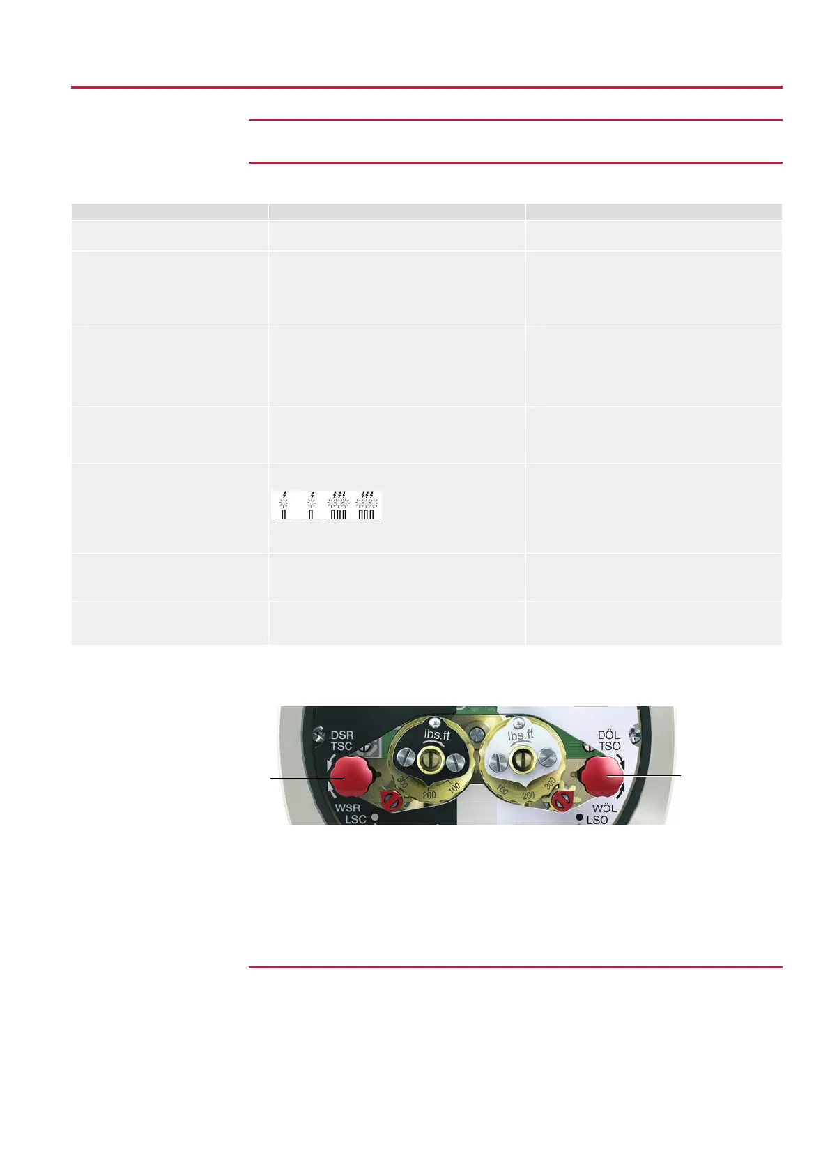
Switch check
The red test buttons [1] and [2] are used for manual operation of the switches:
Figure37: Test buttons
1. Turn test button [1] in direction of the TSC arrow: Torque switch CLOSED trips.
2. Turn test button [2] in direction of the TSO arrow: Torque switch OPEN trips.
If the actuator is equipped with DUO limit switches (option), the intermediate position
switches (LSA and LSB) will be operated at the same time as the torque switches.
1. Turn test button [1] in direction of the LSC arrow: Limit switch CLOSED trips.
2. Turn test button [2] in direction of the LSO arrow: Limit switch OPEN trips.
12.2
Motor protection (thermal monitoring)
Thermal switches are provided in the motor winding to monitor the motor winding tem-
perature. The thermal switches trip as soon as the max. permissible winding tempera-
ture has been reached.
Possible causes Overload, running time exceeded, max. number of starts exceeded, ambient tempera-
ture exceeded.
 Loading...


