Assembly
14
5.3.1
Overview on coupling variants
Design
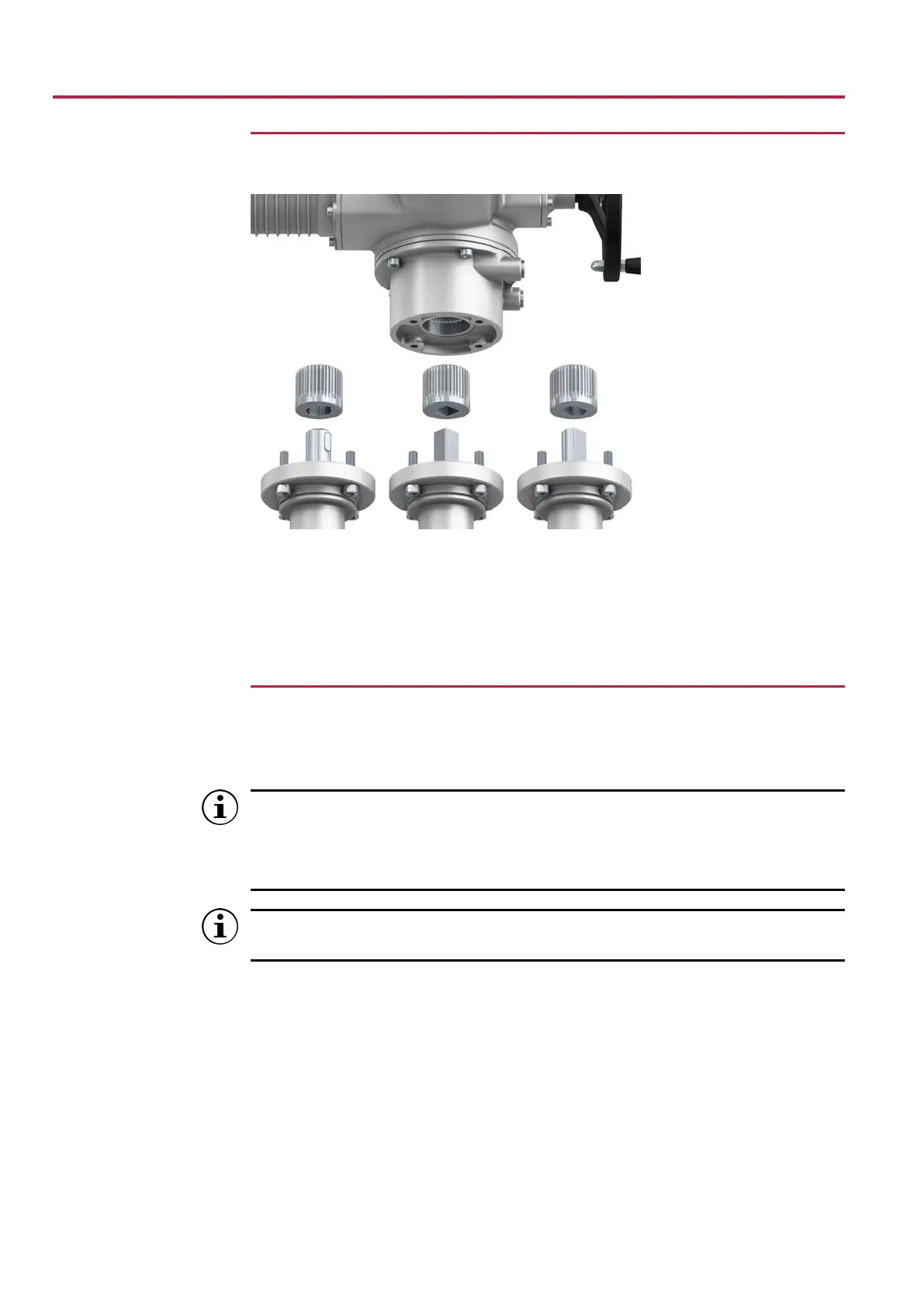
Figure8: Valve attachment via coupling
[1] Bore with keyway [2] Square bore
[3] Two-flat
Application • For valves with connections according to MSS SP 101 [ISO 5211]
• For rotating, non-rising valve stem
5.3.1.1
Mount actuator (with coupling)
Unbored couplings or couplings with pilot bore must be machined to match the valve
shaft prior to mounting the actuator to the valve (e.g. with bore and keyway, two-flat or
square bore).
Valve and actuator must be assembled in the same end position. As standard,
the actuator is supplied in end position CLOSED.
a) Recommended mounting position for butterfly valves: End position CLOSED.
b) Recommended mounting position for ball valves: End position OPEN.
We recommend applying liquid thread sealing material to the screws to avoid
contact corrosion.
Assembly steps 1. If required, move actuator to the same end position as the valve using the hand-
wheel.
2. Clean mounting faces, thoroughly degrease uncoated mounting surfaces.
3. Apply a small quantity of grease to the valve shaft [2].
4. Place coupling [1] onto valve shaft [2] and secure against axial slipping by using a
grub screw [3] or a clamping washer and a screw with curved spring lock washer
[4]. Thereby, ensure that dimensions X, Y or L are observed (refer to figure and ta-
ble Mounting positions for coupling).
 Loading...


