Commissioning (basic settings)
29
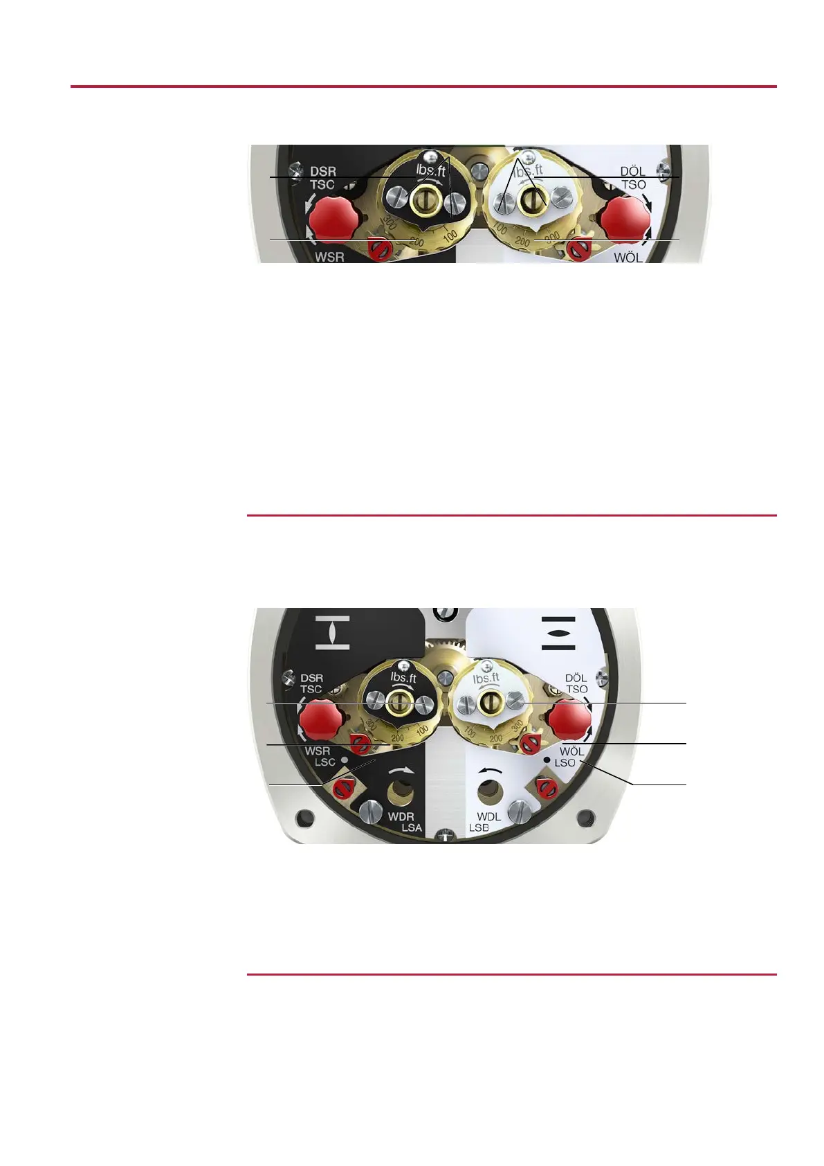
Figure27: Torque switching heads
[1] Torque switching head black in direc-
tion CLOSE
[2] Torque switching head white in direc-
tion OPEN
[3] Lock screws [4] Torque dials
How to proceed 1. Loosen both lock screws [3] on torque dials.
2. Turn torque dial [4] to set the required torque. Example:
ð Black torque switching head set to approx. 185ft-lb [250Nm] for direction
CLOSE.
ð White torque switching head set to approx. 150ft-lb [200 Nm] for direction
OPEN
3. Fasten lock screws [3] again.
Information: Maximum tightening torque: 0.2 – 0.3 ft-lb [0.3 – 0.4 Nm]
ð The torque switch setting is now complete.
10.4
Limit switch setting
The limit switches monitor the travel. When reaching the preset position, switches are
operated.
Figure28: Setting elements for limit switches
[1] Setting spindle: End position CLOSED
(black section)
[2] Pointer: End position CLOSED (black
section)
[3] Mark: End position CLOSED set (black
section)
[4] Setting spindle: End position OPEN
(white section)
[5] Pointer: End position OPEN (white sec-
tion)
[6] Mark: End position OPEN set (white
section)
10.4.1
Set end position CLOSED (black section)
1. Engage manual operation.
2. Turn handwheel clockwise until valve is closed.
3. Press down and turn setting spindle [1] with screw driver in direction of the arrow
and observe the pointer [2]: While a ratchet click is felt and heard, the pointer [2]
moves 90° every time.
 Loading...


