3.10.8 Replacing the Servomotor for a Feed water Valve
READ THOROUGHLY BEFORE COMMENCING WORK
1. Firstly, power to the system must be removed in order to make mechanical adjustments.
2. In order to ensure that the valve is fully closed the following pictures must be followed:
It is essential to check the feed water valve position and adjust this to the close position. This is done
using the crank and checking the position of the valve stem out of the valve.
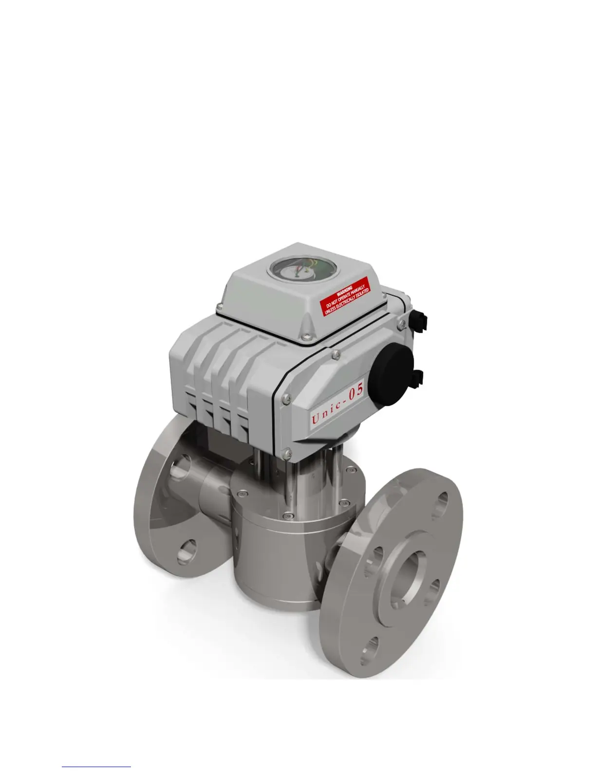
3. The coupling must then be attached to the feed water valve and correctly aligned as in the picture,
and the servomotor must be at exactly 90 degrees to the feed water valve (flow through the valve).
When the servomotor is supplied, it comes in the 0 degree position.
Figure 3.10.8.i Feed water Valve and Industrial Servomotor
 Loading...