4 TOTAL DISSOLVED SOLIDS MANAGEMENT
4.1 Philosophy of TDS Control System
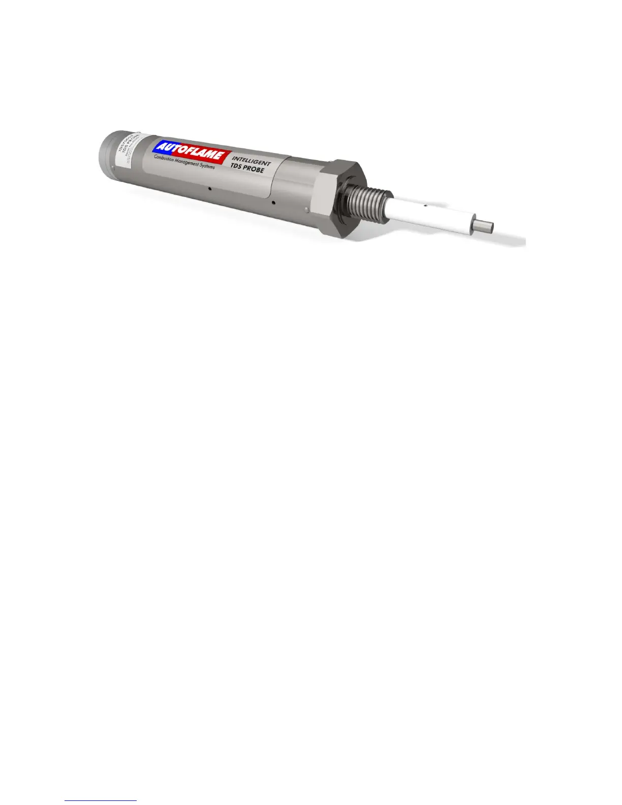
Figure 4.1.i TDS Probe
To manage a steam boiler for optimum efficiency and reliability an important requirement is to ensure
that the Total Dissolved Solids (TDS) in the water are measured and controlled to the right level for that
boiler. It is generally accepted that for water tube boilers the level of TDS measured should not exceed
1,500 PPM by volume and for smoke tube boilers the TDS should not be higher than 2,500 PPM by
volume. The figures stated are not definitive and in all applications the recommendations of the boiler
manufacturer or water treatment chemist should be implemented.
1. It has been established that the conductivity of water is proportional to the measured TDS as
long as the temperature remains constant. Any variations in temperature will affect the measured
conductivity by nominally 2% per 1°C. It follows that the temperature of the water must be measured
and the conductivity reading must be adjusted before a TDS reading can be extrapolated from this line
of data. The Autoflame system incorporates a temperature measurement sensor in the steam drum to
establish the steam temperature. This data stream is used to constantly correct the conductivity value.
2. A second variable that effects the conductivity measurement is polarization of the water
sample. This occurs when electrical energy from the probe builds up a relatively tiny offset above or
below the earth (0 volt value). This polarization value is typically noticeable when a continuous
frequency is being emitted from the probe as part of the conductivity measurement method. The
Autoflame system deals with the potential problem of polarization in the following manner. The probe
measures any build-up of voltage potential above or below earth or 0V in the water sample. The
measured polarization voltage data is used to modify the conductivity calculation. The Autoflame
system emits electrical energy at a rate of 10x 300 microsecond pulses every second. This translates
into a method where we are emitting electrical energy for 0.6% of the sample time. All other
manufacturers who use the frequency method are emitting electrical energy for 100% of the sample
time. It follows that the polarization problem in these cases would be 167 times greater!
3. A third problem that affects the accuracy of the TDS measurement is the build up of scale on
the probe electrode. By design the water sampling container has been arranged so that the turbulence
created during the blow down sequence will ensure that the probe remains effectively free of scale or
deposited solids that could be held in suspension.
4. The sampling container has a known orifice size. From this it is possible to calculate the
percentage losses due to surface blowdown. This is possible because the following parameters are
known – hole size, temperature, pressure, pressure drop across the solenoid and the time that the
solenoid is open for.
It can be seen from the above that the Autoflame TDS system deals succinctly with three of the main
problem areas that are encountered when designing an accurate TDS control solution.
 Loading...