Home
AUTOFLAME
Measuring Instruments
Mk7
AUTOFLAME Mk7 User Manual
5
of 1
of 1 rating
152 pages
Give review
Manual
Specs
To Next Page
To Next Page
To Previous Page
To Previous Page
Loading...
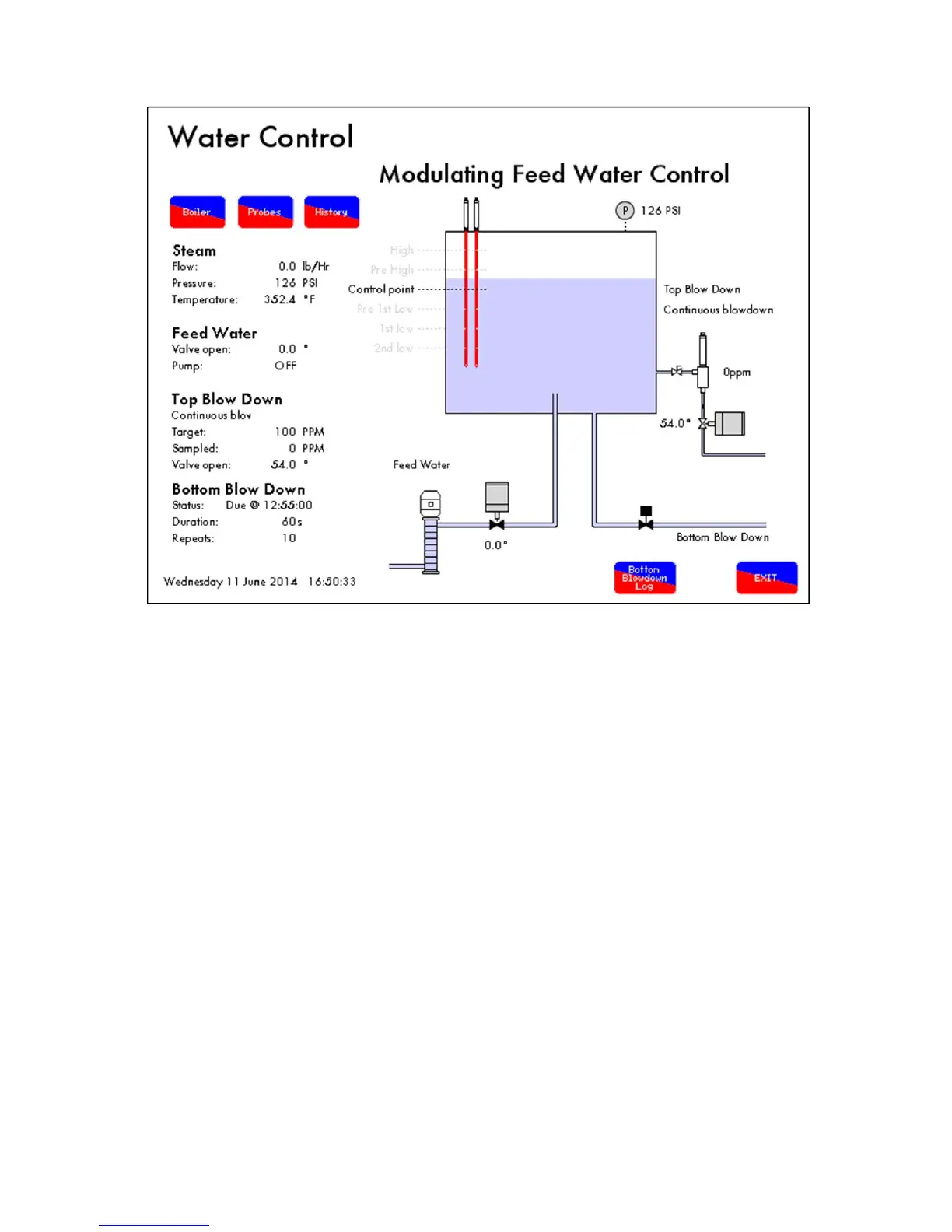
Figure 5.4.ii Water Level Screen
The next time for the bottom blowdown wil
l show in
the bottom right corner of the screen, see Figure
5.4.ii, as well as the duration of
that next blowdown with its repeats.
When it is due, the status will
show IMMINENT, and when it begins th
is will change to IN PROGRESS.
5 Bottom Blowdown
Page 88
Mk7 Manual: Expansion Board Set-Up Guide
October 2014
97
99
Table of Contents
Important Notes
5
Introduction
11
Water Level Schematic
12
Water Level Features
13
Set-Up
15
Dimensions
16
Terminals Description
17
Electrical Specification
20
Options
21
Commissioning Water Level
30
Operational Checks
33
First Outs Set-Up
34
Integrating Other Water Level Controls with Autoflame
36
Water Level Probes
37
Steam Flow Induced Surge
38
Schematic Explanation of the Water Level Probe Operation
39
Capacitance Probe
40
Schematic of the Probe Sampling Software
41
Capacitance Probe – Externally Mounted Pots
42
Capacitance Probe – Internally Mounted Pots
44
Capacitance Probe – Installation for a Water Tube Boiler
46
External Probe Chamber Dimensions
47
Capacitance Probe Specification
48
Water Level Treatment
49
Nd Low Probe
50
Modulating Feed Water Valve
51
Feed Water Valve Specification
52
Bronze Liner
53
Feed Water Valve Sizing Calculations
54
Flanged Feed Water Valve
55
Threaded Feed Water Valve
56
Replacing the Servomotor for a Feed Water Valve
58
Storage, Operation and Maintenance
60
Total Dissolved Solids Management
61
TDS Probe Calibration
62
Method of TDS Control
66
Continuous TDS Blowdown
67
Installation of TDS Probe Assembly
68
TDS Probe and Autoflame Sampling Vessel
69
Top Blowdown Adjusters
70
Sample Routine
72
Relationship between Conductivity, Temp and TDS Values
73
Bottom Blowdown
74
Bottom Blowdown Time Reduction
75
Bottom Blowdown Valve Drawings
78
Front Facia and Dimensions
80
Bottom Blowdown Configuration
81
Commissioning Bottom Blowdown Module with M.M
85
Battery Test
89
Bottom Blowdown Timer Configuration
90
Commissioning Standalone Bottom Blowdown Module
93
Bottom Blowdown Operation
97
Further Bottom Blowdown Time Reduction Savings Calculations
100
Shunt Switch
106
Steam and Heat Flow Metering
107
Steam Flow Metering Incorporating a Deaerator
112
Calculations for Steam Flow Metering with Deaerator
113
Steam Flow Metering Without Deaerator
114
Steam Flow Metering Without Deaerator, with Economiser
115
Steam Flow Metering with Deaerator
116
Steam Flow Metering with Deaerator and Economiser
117
Steam Flow Metering with Deaerator and Feed Water Sensor
118
Heat Flow Metering
119
Heat Flow Metering Calculation
120
Heat Flow Metering
121
Heat Flow Metering with Economiser
122
Draft Control
123
Set-Up
125
Commissioning with Draft Control
127
Draft Control Operation
142
Trim Operation
144
Troubleshooting and Diagnostics
145
5
Based on 1 rating
Ask a question
Give review
Questions and Answers:
Need help?
Do you have a question about the AUTOFLAME Mk7 and is the answer not in the manual?
Ask a question
AUTOFLAME Mk7 Specifications
General
Brand
AUTOFLAME
Model
Mk7
Category
Measuring Instruments
Language
English
Related product manuals
AUTOFLAME Mk8 EGA
82 pages
 Loading...