Installation, Wiring,
and Specifications
2--5
Installation, Wiring, and Specifications
DL105 PLC User Manual, 3rd Edition
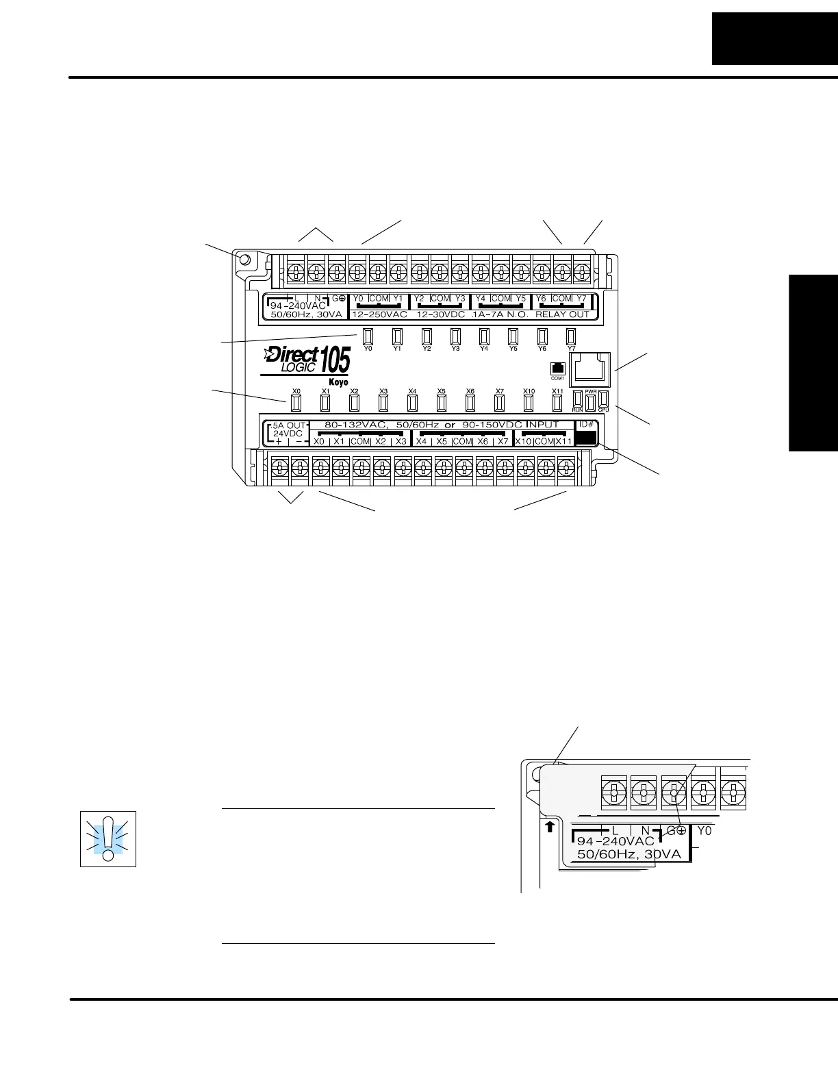
Orientation to DL105 Front Panel
All c onnections, indicators, and labels on the DL105 Micro PLCs are located on its
front panel. Please refer to the drawing below.
ID# Area
Output Status Indicators
Input Status Indicators
Mounting hole (1 of 2)
Auxiliary Supply Terminals
Communications Port
Discrete Input Terminals
Discrete Output TerminalsExternal Power Input
Run, Power, CPU
Indicators
Output Circuit Power Input
(for DC Output versions only)
The upper connector accepts external power connections on the left-most
terminals. The remainder of the terminals accept wires for the eight output points
and their commons. On DC output versions, the end terminal on the right accepts
power for the output stage. In many applications the external power to the Micro PLC
also powers the loads and output circuit, so this terminal block groups them together.
The lower connector delivers the internal +24VDC auxiliary supply output on the two
left-most terminals (AC-powered units only). On DC-powered units, the terminals
are not used. The remaining terminals accept wires for the ten discrete inputs and
their commons. In many applications the auxiliary +24VDC output also powers the
input circuit, so this terminal block groups them together.
To access the terminals just pull forward
on the corner of the terminal cover where it
is marked “pull”, as s hown to the right.
After exposing the connector block, it may
be removed from the unit if desired.
WARNING: For some applications,
field device power may still be present
on the terminal block even though the
Micro PLC is turned off. To minimize
the risk of electrical shock, check all
field device power before you expose
or remove either connector. Be sure to
leave the covers normally closed.
P
U
L
L
Pull Here (terminal block cover, 1 of 2)
Accessing the
I/O Terminals


 To Next Page