Installation, Wiring,
and Specifications
2--41
Installation, Wiring, and Specifications
DL105 PLC User Manual, 3rd Edition
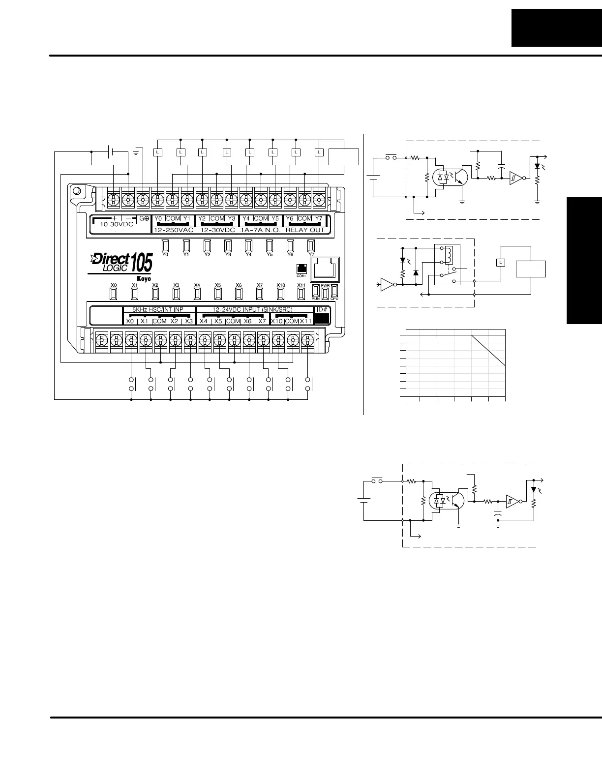
The F1--130DR--D Micro PLC features ten DC inputs and eight relay outputs. The
following diagram shows a typical field wiring example. The DC external power
connection uses three terminals at the top left as shown.
Input Point Wiring
+
Output Point Wiring
Ground
Power Input Wiring
AC or DC
Supply
10 -- 30VDC
+--
AC or DC
Supply
Equivalent Output Circuit
To other circuits in bank
Common
Output
+V
Derating Chart for Relay Outputs
0
2
4
6
8
Points
0102030405060
Ambient Temperature (C/F)
32 50 68 86 104 122 140
C
F
Optical
Common
Input
+V
Isolator
To other circuits in bank
+
--
Equivalent Circuit,
Standard Inputs (X4 -- X11)
7A
7A
6A
10W
The ten DC input channels use terminals
on the bottom connector. Inputs are
organized into two banks of four, plus one
bank of two. Each bank has an isolated
common terminal, and may be wired as
sinking or sourcing inputs. The wiring
example above shows all commons
connected together, but separate supplies
and common circuits may be used. The
equivalent circuit for standard inputs is
shown above, and the high-speed input
circuit is shown to the right.
Equivalent Circuit, High-
Speed Inputs (X0 -- X3)
Optical
Common
Input
+V
Isolator
To other circuits in bank
+
--
The eight output channels use terminals on the top connector. Outputs are
organized into four banks of two normally-open relay contacts. Each bank has a
common terminal. The wiring example above shows all commons connected
together, but separate supplies and common circuits may be used. The equivalent
output circuit shows one channel of a typical bank. The relay contacts can switch AC
or DC voltages.
The F1--130DR--D does not include a +24V output, as do most other DL105 PLCs.
Since this unit requires +24V as the main supply input, it it usually most economical
to use the same supply to power suitable field devices. In the wiring diagram above,
F1--130DR--D
I/O Wiring Diagram
No Auxiliary +24V
Power Supply