Installation, Wiring,
and Specifications
2--33
Installation, Wiring, and Specifications
DL105 PLC User Manual, 3rd Edition
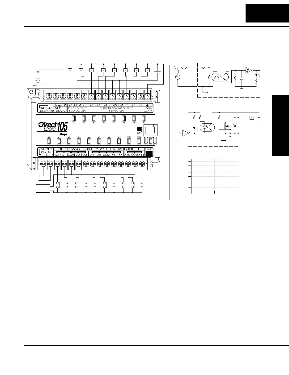
The F1--130AD Micro PLC features ten AC inputs and eight DC outputs. The
following diagram shows a typical field wiring example. The AC external power
connection uses three terminals at the top left as shown.
+
--
12 -- 24 VDC
Input Point Wiring
Output Point Wiring
Ground
Neutral
Line
Power
Input Wiring
+
--
to field
AC or DC
Supply
devices
Equivalent Input Circuit
Optical
Common
Input
+VIsolator
To other circuits in bank
Equivalent Output Circuit
To all other output circuits
+V
Common
Output
+V
+
--
Derating Chart for DC Outputs
0
2
4
6
8
Points
0102030405060
Ambient Temperature (C/F)
32 50 68 86 104 122 140
C
F
0.3A (8 ckts), 0.5A (4 ckts)
0.6A (8 ckts), 1.0A (4 ckts)
Y2 -- Y7
Y0 -- Y1
Fuse or
C.B.
Fuse
or
C.B.
The ten AC input channels use terminals on the bottom connector. This input type
also works for high-voltage DC signals. Inputs are organized into two banks of four,
plus one bank of two. Each bank has an isolated common terminal. In the case of DC
input signals, the input may be wired in as either the sourcing or sinking type. The
wiring example above shows all commons connected together, but separate
supplies and common circuits may be used. The equivalent input circuit shows one
channel of a typical bank.
The eight current sinking DC output channels use terminals on the top connector.
The three common terminals are internally connected, meaning all outputs actually
share the same electrical common. The wiring example above shows all commons
connected together, because it is best to s hare the common c urrent among the three
terminal connections. Note the requirement for external power on the end
(right-most) terminal. The equivalent output circuit shows one channel of the bank of
eight.
The F1--130AD has a +24V supply output to power external devices. The output is
rated at 0.5 Amperes, and includes short-circuit protection and full isolation from
internal CPU circuitry. These features make it ideal for powering sensors, solenoids,
and other field devices. In fact, it can be used as the supply for loads in the DC output
circuits. Since the outputs are the sinking type, you’ll need to connect +24V to the
output commons. Be sure the combined load currents do not exceed 0.5 A. Note that
on the F1--130AD, the +24V auxiliary output is not high enough to power its input
circuits (input ON threshold is 90VDC).
F1--130AD
I/O Wiring Diagram
Auxiliary +24V
Power Supply