Installation, Wiring,
and Specifications
2--34
Installation, Wiring, and Specifications
DL105 PLC User Manual, 3rd Edition
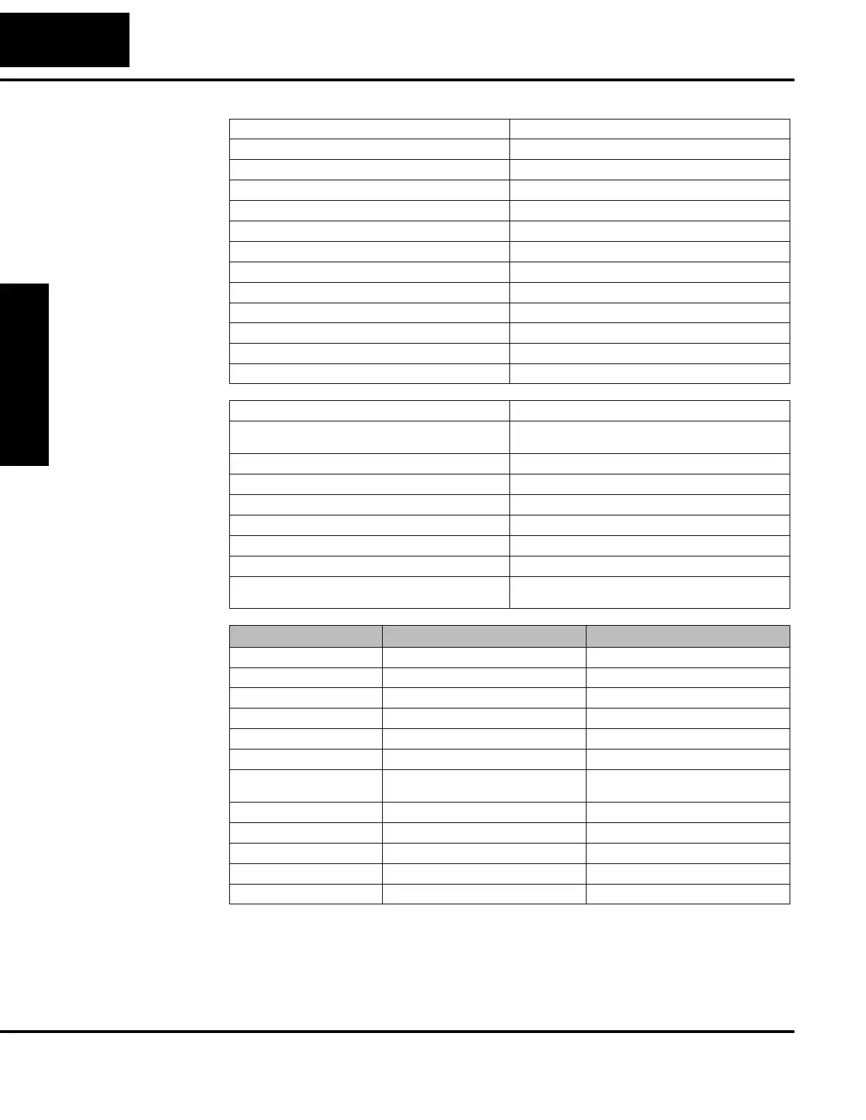
External Power Requirements 100 -- 240 + 10% --15%
Communication Port K--Sequence, 9600 baud, 8 data bits, odd parity
Programming cable type D2--DSCBL
Internal Field Supply Ratings +24VDC , 0.5A maximum, isolated
Operating Temperature
32 to 140 F(0to60_ C)
Storage Temperature
--4to158 F (-- 20 to 70_ C)
Relative Humidity 5 to 95% (non-condensing)
Environmental air No corrosive gases permitted
Vibration MIL STD 810C 514.2
Shock MIL STD 810C 516.2
Noise Immunity NEMA ICS3--304
Terminal Ty pe Removable
Wire Gauge One AWG14 or two AWG16, AWG24 minimum
Input Voltage Range for ON condition 80 -- 132 VAC, or 90 -- 150 VDC
Input Current 6 mA @ 132 VAC
6.8 mA @ 150 VDC
Maximum Voltage 132 VAC, or 150 VDC
ON Current/Voltage >4mA@80VAC,or90VDC
OFF Current/Voltage <2mA@45VAC,or60VDC
OFF to ON Response <8mS
ON to OFF Response <15 mS
Status Indicators Logic Side
Commons 4 channels / common x 2 banks,
2 channels / common x 1 bank
Parameter Pulse O utputs, Y0 -- Y1 Standard Outputs, Y2 -- Y7
Operating Voltage 5--30VDC 5--30VDC
Peak Voltage 60 VDC (7 kHz maximum frequency) 60 VDC
On Voltage Drop 0.4 VDC @ 0.25A 0.4 VDC @ 0.5A
Max Current (resistive) 0.5 A / point (subject to derating) 1.0 A / point (subject to derating)
Max leakage current
15 μA@30VDC 15 μA@30VDC
Max inrush current 1.5 A for 10 mS, 0.5 A for 100 mS 3Afor10mS,1Afor100mS
Extenal DC power required 10 -- 30 VDC @30 mA,
plus load current
10 -- 30 VDC @30 mA,
plus load current
OFF to ON Response
<10 μS 3.5 μS
ON to OFF Response
<70 μS 110 μS
Status Indicators Logic Side Logic Side
Commons Internally connected Internally connected
Fuses None None
F1--130AD
General
Specifications
AC Input
Specifications
DC Output
Specifications