Installation, Wiring,
and Specifications
2--26
Installation, Wiring, and Specifications
DL105 PLC User Manual, 3rd Edition
DL105 DC output circuits are h igh-performance MOSFET switches with low
on-resistance and fast switching times. Please note the following characteristics
which are unique to the DC output type:
S There is only one electrical common for all eight outputs, even though
there are three common terminals. All eight outputs belong to one bank.
S The output switches are current-sinking only. However, you can still use
different DC voltages from one load to another.
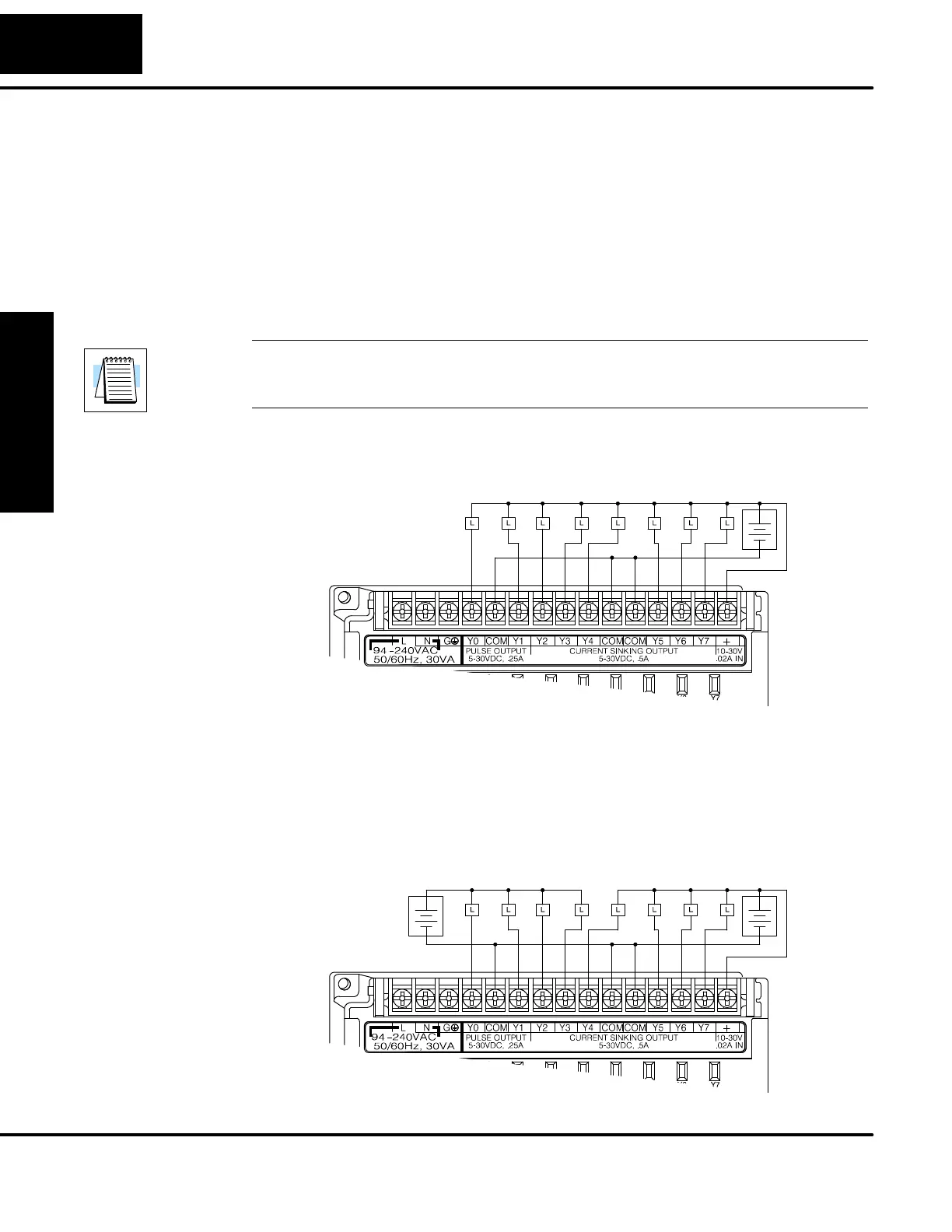
S The output circuit inside the PLC requires external power. The supply
(--) must be connected to a common terminal, and the supply (+)
connects the the right-most terminal on the upper connector.
NOTE: Always connect all three common terminals together at the connector with
short wires (do not leave some common terminals unconnected).This provides
three connections to share the load return current, enhancing reliability.
In the example below, all eight outputs s hare a c ommon supply. It may be external as
shown, or they may use the auxiliary +24VDC supply when available.
Output Point Wiring
+
--
+24 VDC
External
Supply
In the next example below, the outputs have “split” supplies. The first four outputs are
using a +5 VDC supply, and the last four are using a +24 VDC supply. However, you
can split the outputs among any number of supplies, as long as:
S all supply voltages are within the specified range
S all output points are wired as sinking
S all source (--) terminals are connected together
Output Point Wiring
+
--
+
--
+24 VDC
External
Supply
+5 VDC
External
Supply
DC Output
Wiring Methods


 To Next Page