Installation, Wiring,
and Specifications
2--16
Installation, Wiring, and Specifications
DL105 PLC User Manual, 3rd Edition
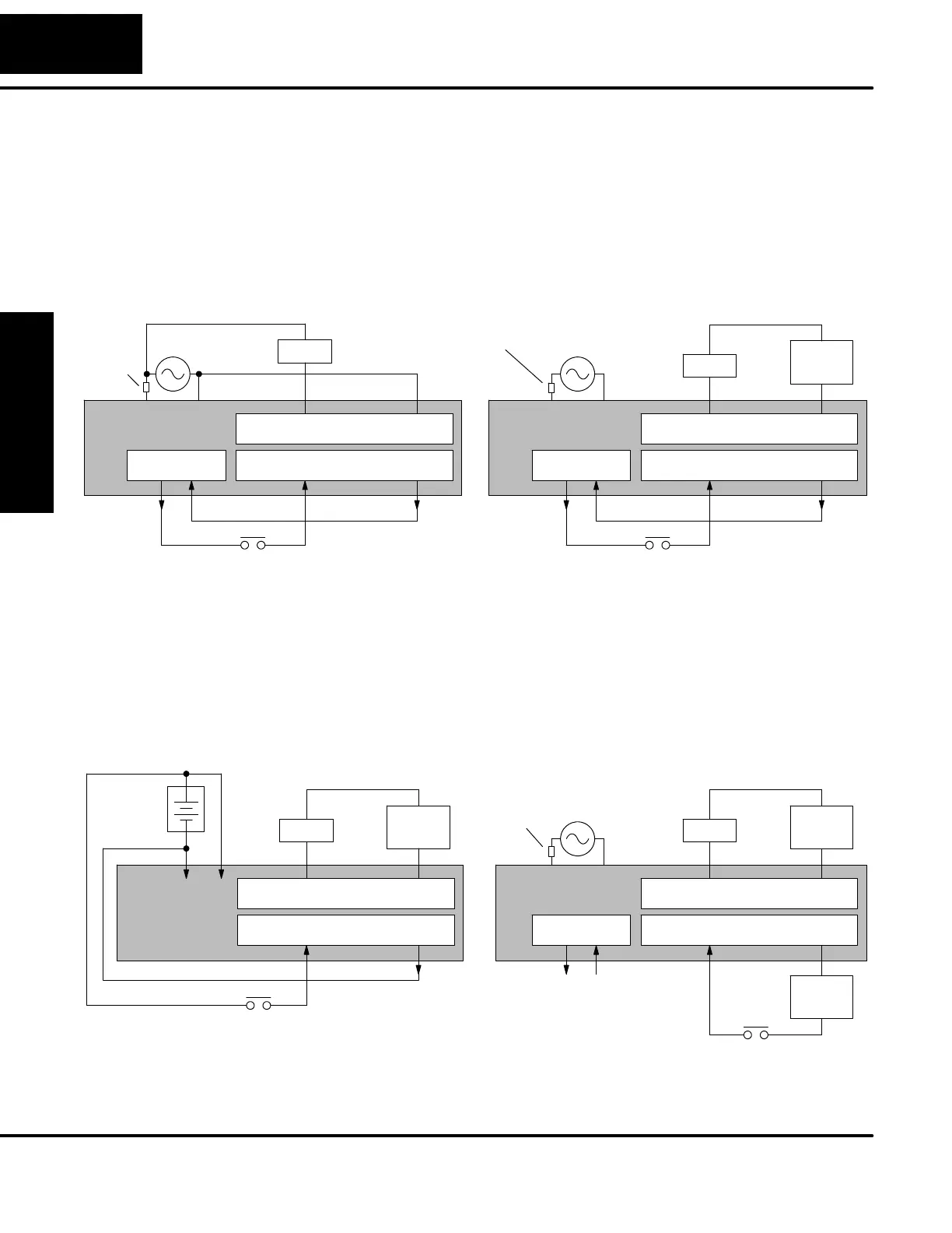
In some applications it will be necessary to power the input devices from one power
source, and to power output loads from another source. Loads often require
high-energy AC power, while input sensors use low-energy DC. If a machine
operator is likely to come in close contact with input wiring, then safety reasons also
require isolation from high-energy output circuits. It is most convenient if the loads
can use the same power source as the Micro PLC, and the input sensors can use the
auxiliary supply, as shown to the left in the figure below.
If the loads cannot be powered from the Micro PLC supply, then a separate supply
must be used as shown to the right in the figure below.
10 Discrete Inputs Commons
Commons8 Discrete O utputsPower Input
PLC
DL105
+--
Loads
+24VDC Out
AC Power
10 Discrete Inputs Commons
Commons8 Discrete O utputsPower Input
PLC
DL105
+--
Loads
+24VDC Out
AC Power
Load
Supply
Fuse or
Circuit
Breaker
Fuse or
Circuit
Breaker
Some applications will use the Micro PLC power source to also power the input
circuit. This typically occurs on a DC-powered DL105, as shown in the drawing
below to the left. The inputs share the PLC power source supply, while the outputs
have their own separate supply.
A worst-case scenario, from a cost and complexity view-point, is an application
which requires separate power sources for the PLC, input devices, and output loads.
The example wiring diagram below on the right shows how this can work, but also
that the auxiliary supply out is an unused resource. For these reasons, you’ll
probably want to avoid this situation if possible.
10 Discrete Inputs Commons
Commons8 Discrete O utputsPower Input
PLC
DL105
Loads
+24VDC Out
AC Power
Load
Supply
Input
Supply
10 Discrete Inputs Commons
Commons8 Discrete O utputsPow-
er
Input
PLC
DL105
Loads
DC Power
+
--
+--
Load
Supply
Fuse or
Circuit
Breaker
Powering I/O
Circuits Using
Separate Supplies
 Loading...

