Installation, Wiring,
and Specifications
2--13
Installation, Wiring, and Specifications
DL105 PLC User Manual, 3rd Edition
The following guidelines provide general information on how to wire the I/O
connections to DL105 Micro PLCs. For specific information on wiring a particular
PLC refer to the corresponding specification sheet further in this chapter.
1. Each terminal connection of the DL105 PLC can accept one 14 AWG wire
or two 16 AWG size wires. Do not exceed this recommended capacity.
2. Always use a continuous length of wire. Do not splice wires to attain a
needed length.
3. Use the shortest possible wire length.
4. Use wire trays for routing where possible.
5. Avoid running wires near high energy wiring.
6. Avoid running input wiring close to output wiring where possible.
7. To minimize voltage drops when wires must run a l ong distance , consider
using multiple wires for the return line.
8. Avoid running DC wiring in close proximity to AC wiring where possible.
9. Avoid creating sharp bends in the wires.
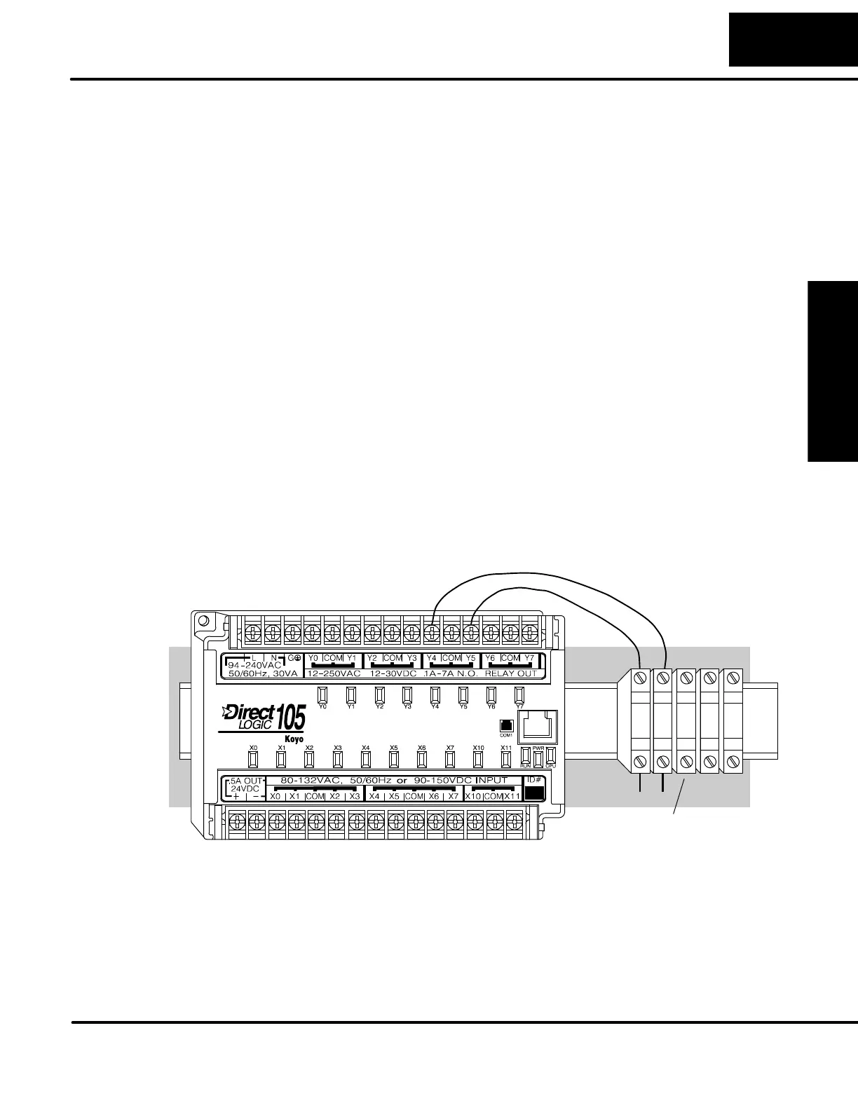
Input and Output circuits on DL105 Micro PLCs do not have internal fuses. However,
the +24V Auxiliary Supply is current-limited. In order to protect y our Micro PLC, we
suggest you add external fuses to your I/O wiring. A fast-blow fuse, with a lower
current rating than the I/O bank’s common current rating can be wired to each
common. Or, a fuse with a rating of slightly less than the maximum current per output
point can be added to each output. Refer to the Micro PLC specification sheets
further in this chapter to find the maximum current per output point or per output
common. Adding the external fuse does not guarantee the prevention of Micro PLC
damage, but it will provide added protection.
External Fuses
(shown with DIN Rail, Fuse Blocks)
All DL105 Micro PLCs have a fixed I/O configuration. It follows the same octal
numbering system used on other DirectLOGICfamilyPLCs,startingatX0andY0.
The letter X is always used to indicate inputs and the letter Y is always used for
outputs.
The I/O numbering always starts at zero and does not include the digits 8 or 9. The
addresses are typically assigned in groups of 8 or 16, depending on the number of
points in an I/O group. For the DL105 the ten inputs use reference numbers X0 -- X7
and X10 -- X11. The eight output points use references Y0 -- Y7.
Planning the
Wiring Routes
Fuse Protection
for Input and
Output Circuits
I/O Point
Numbering