Installation, Wiring,
and Specifications
2--42
Installation, Wiring, and Specifications
DL105 PLC User Manual, 3rd Edition
the external power source for the unit also powers the input circuitry. The same
external supply can power both input and output circuits, because they are both
isolated from the internal logic circuitry.
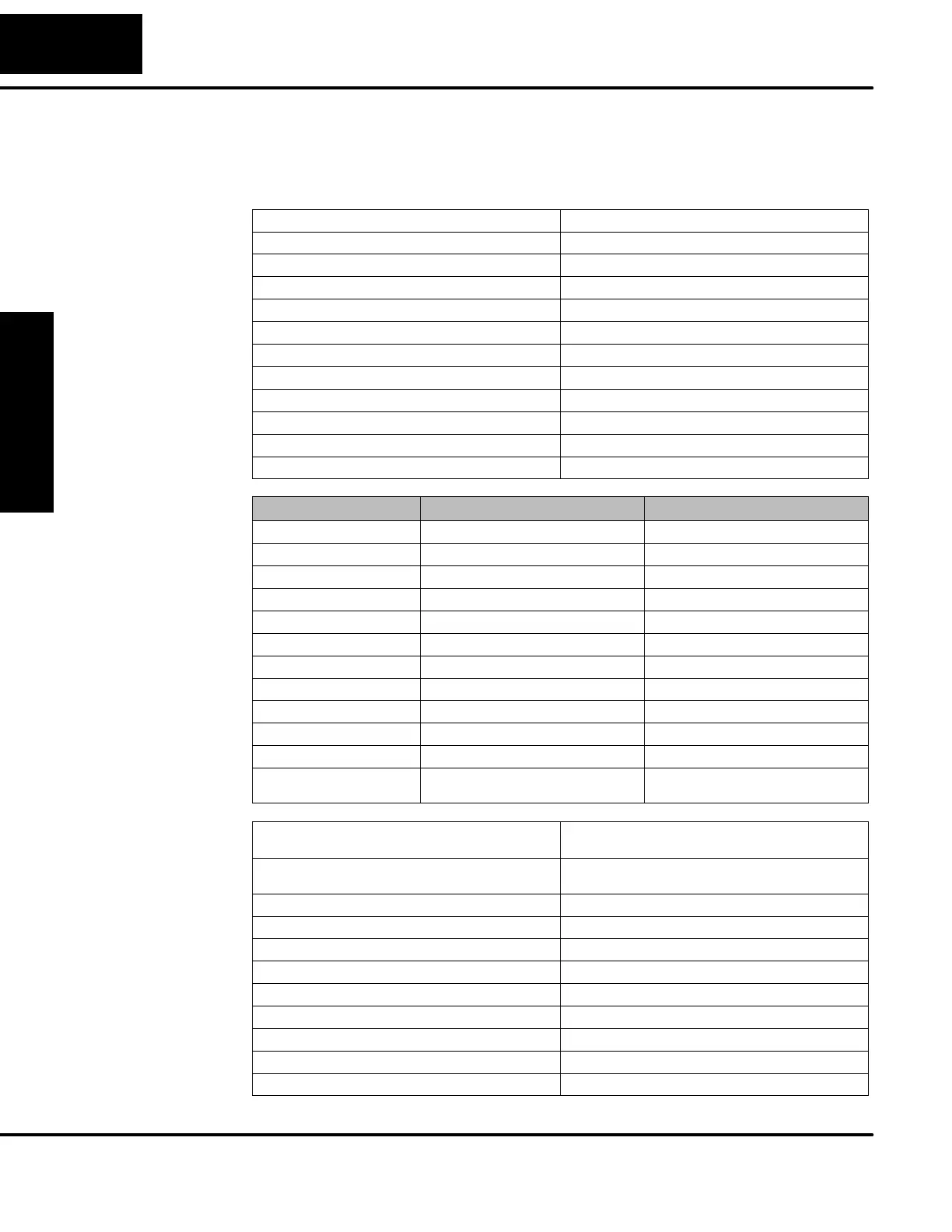
External Power Requirements 10--30VDC, 1.5A
Communication Port K--Sequence, 9600 baud, 8 data bits, odd parity
Programming cable type D2--DSCBL
Operating Temperature
32 to 140 F(0to60_ C)
Storage Temperature
--4to158 F (-- 20 to 70_ C)
Relative Humidity 5 to 95% (non-condensing)
Environmental air No corrosive gases permitted
Vibration MIL STD 810C 514.2
Shock MIL STD 810C 516.2
Noise Immunity NEMA ICS3--304
Terminal Ty pe Removable
Wire Gauge One AWG14 or two AWG16, AWG24 minimum
Parameter High--Speed Inputs, X0 -- X3 Standard DC Inputs X4 -- X11
Input Voltage Range 10 -- 26.4 VDC 10 -- 26.4 VDC or 21.6 -- 26.4 VAC
Maximum Voltage 30 VDC (5 kHz maximum frequency) 30 VDC
Minimum Pulse Width
100 μs
N/A
ON Voltage Level >9.0VDC >9.0VDC
OFF Voltage Level <2.0VDC <2.0VDC
Input Impedance
2.8 kΩ @12--24VDC 2.8 kΩ @12--24VDC
Minimum ON Current >3 mA >3 mA
Maximum OFF Current <0.5mA <0.5 mA
OFF to ON Response
<50 μS
2 -- 8 mS, 4 mS typical
ON to OFF Response
<50μS
2 -- 8 mS, 4 mS typical
Status Indicators Logic side Logic side
Commons 4 channels / common x 1 bank 4 channels / common x 1 bank,
2 channels / common x 1 bank
Operating Voltage 12 -- 250 VAC, 12 -- 30 VDC @ 7A,
30 -- 150 VDC @ 0.5A, resistive
Output Current 7A / point (subject to derating)
14A / common
Maximum Motor Load 1/3 HP
Maximum Voltage 265 VAC, 150 VDC
Minimum Off Resistance 100 meg ohms @ 500 VDC
Smallest Recommended Load 10 mA
OFF to ON Response 15 ms
ON to OFF Response 5ms
Status Indicators Logic Side
Commons 2 channels / common x 4 banks
Fuses None (external recommended)
F1--130DR--D
General
Specifications
DC Input
Specifications
Relay Output
Specifications